Avidyne TAS605 Installation in a Socata TB20GT
This article describes the installation of the Avidyne TAS605 traffic warning
system in a Socata TB20GT. It was originally done around 2012. In 2025 the TAS605 processor was upgraded with a TAS605A which also receives ADS-B data and merges it with targets acquired via the TAS function. This upgrade is described nearer the end of the article.
Objective
There are several fairly obvious reasons for wishing to "see" traffic:
1) To reduce the chance of a mid-air collision
The probability of a mid-air is extremely small, but most of them are 100%
fatal. The UK has around 2 per year. The number of hours flown by GA pilots
in the UK is not known, but taking the known figure of about 20,000 pilots with
valid medicals, and the generally believed annual average flying time of about
30 hours, gives us an order of magnitude for this, of about 1 mid-air per 300k
hours. Not a good case for spending money on it!
What suprises most people is that, as far as is known, all of the UK mid-airs
since WW2 have been in VMC. This is probably because of the far lower traffic
density in IMC. Enroute traffic is limited to pilots with instrument qualifications
and circuit flying is "officially" not allowed in IMC.
The case for spending money on it gets even worse when one looks at the circumstances
of the mid-air collisions that have happened. Most of them are at very low levels,
usually below 1500ft. There are some notable exceptions such as the RAF
Grob training mid-air which happened at 2900ft, but it appears that most
of those are between flights that are not exactly unrelated. There seem to be
almost no collisions between unrelated aircraft flying enroute at 3000ft or
more.
No transponder-based traffic detection device will work unless the target has
a transponder, it is switched on, and for a useful warning (relative altitude
included) the transponder has to be Mode C or Mode S. A proportion of GA has
no transponder, or the pilot turns it off (due to stupid training, or a misplaced
concern for "civil liberties" i.e. he doesn't want to be seen on radar).
So a percentage of traffic will never be detected anyway. However, from years
of flying under a radar service several things are quite obvious to me, for
the UK:
- most reported contacts are never spotted (this is normal  - everybody has that problem)
- of those that are spotted, nearly all are well below me (are estimated to
be at 2000ft or below)
- of those that are spotted and reported "altitude unknown" (non-transponding
i.e. primary rardar return only, or transponding Mode A only) nearly all are
estimated below 1000ft
It would thus appear that the biggest benefit of a traffic warning system is
at low altitudes, with the benefit reducing at very low altitudes. An exception
to this may be helicopters which routinely fly very low, but most will have
a transponder.
2) To improve awareness of traffic in the circuit which one is joining or departing
A lot of mid-airs occur near airfields where one cannot avoid being at a low
altitude if arriving or departing.
It's often hard to spot other traffic in or near the circuit. Aircraft are
inherently hard to see, and a target on a genuine collision course will be a
stationary point in the field of view (for both pilots involved) so doubly hard
to spot. Also some pilots do not report their location with any accuracy; sometimes
accidentally, and sometimes deliberately to get a joining or landing clearance
before somebody else!
A fairly common situation is where e.g. someone reports "downwind"
but you (joining crosswind) can't see him. He could be anywhere from several
miles upwind (especially if doing a downwind join) or he could be late-downwind.
Or he could be right where you are joining... Some people fly massive circuits,
extending miles away from the airfield...
Therefore, a traffic detection device should improve one's awareness of circuit
traffic - even if it fails to show non-transponding aircraft.
3) To improve awareness of traffic, while one is on the ground
With Avidyne or Garmin systems, you can see transponding traffic (both on the
ground and airborne) so e.g. you can see traffic on the final approach before
you enter the runway. This gives an extra layer of safety over ATC keeping track
of who is where, etc.
4) To offer some protection when flying an instrument procedure in Class G
Many instrument procedures are outside controlled airspace and one often finds
traffic flying merrily straight through the procedure track. The platform altitudes
are often 1500, 2000 or 2500ft which a lot of people fly at anyway. I've had
several near-misses when flying an instrument approach in VMC, but in UK Class
G there could be non-radio traffic there in IMC too.
It's clearly much better to first spend money on a ground proximity
warning device but
I already have that.
Other Traffic Detection Systems
In light GA, no traffic detection system has achieved a "critical mass".
FLARM has raised a lot of
hopes, is cheap, but market penetration has been negligible outside the gliding
community, and both aircraft must be equipped with it. Functionally it
is a good system because it uses GPS and, with each aircraft continuously radiating
its 3D GPS position, it is possible to compute mutual trajectories very accurately.
Unfortunately there is no internationally approved frequency on which to radiate
the stuff, which has prevented certified equipment from emerging, which in turn
has prevented anything resembling wide adoption. Also the trajectory algorithm
is not in the public domain; it is somebody's "intellectual property".
If somebody developed a certified product which combines FLARM with the detection
of Mode C targets which displayed the azimuth for Mode C, they would
have a winner.
ADS-B
does not yet exist in Europe (for light GA) but is being introduced and legally
mandated in the USA. Functionally it is similar to FLARM but works on internationally
agreed frequencies (on which there are two incompatible systems, just to make
life interesting) and is certified. It will be many years before it is mandated
in Europe, and in my view it is virtually certain that VFR/OCAS traffic will
be exempted. ADS-B data is already being radiated by large aircraft, and the
data returned under an Enhanced Mode S interrogation amounts to the same thing,
but stupid European (EASA) regulatory practices have
prevented European-registered light GA participating in it.
The only system which has a a relatively wide adoption is the old-style TCAS
like the one described in this article, which interrogates nearby transponders.
These are expensive (usually over €10,000 installed) but they benefit from
Mode C or Mode S transponders being legally required in many airspaces. Today,
it is difficult to do much "going places" flying in Europe without
Mode C or Mode S. There is also a benefit to GA in getting equipped with
a transponder: all aircraft used for public transport, over a certain number
of seats, are legally required to have TCAS, so if you accidentally end up in
the way of something big, they will be able to avoid you. So, for someone contemplating
a TCAS system, the "other half" of the system is already in place
to a large degree.
TAS or TCAS?
The terminology is confusing.
TAS systems advise you of nearby traffic, visually and, with
certified systems, verbally via the aircraft intercom. You don't get advice
on what to do to avoid it. The system described in this article is "TAS".
TCAS systems are mandatory on large aircraft and they offer
advice on avoidance. The advice (called an "RA" - Resolution Advisory")
is mandatory and over-rides ATC instructions and clearances. In fact it over-rides
everything except a GPWS (ground proximity) warning
With TCAS, the two systems communicate with each other and agree an avoidance
strategy, so one pilot is told to climb and the other is told to descend. Standard
practice is that all avoidance is done by climb/descent only, with no directional
changes.
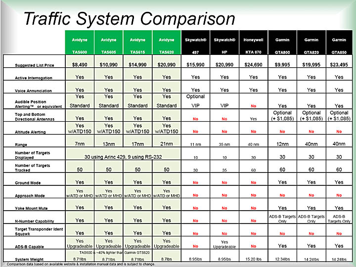
System Choice
There are several main contenders: Avidyne TAS600
series, L3 Skywatch (later called L3 Lynx), Honeywell KT870, Garmin GTX800
series. The following comparison (produced
by Avidyne ) lists
them. No UK installer seemed to know anything about the L3 product. Honeywell
was widely installed about a decade ago but the company has during that time
virtually withdrawn from the GA avionics business so even though the KT870 works
well it is difficult to recommend it. The KT870 installations I know about were
also billed at around €30k which is 2x higher than the Avidyne option.
So it really comes down to Garmin or Avidyne.
A page from the above comparison is here
I made extensive enquiries, in the UK and the USA, regarding Avidyne v. Garmin.
There was no obvious performance difference between the two systems, and it
was apparent that in both cases a careless installation could result in a poorly
working system. In the UK, the Garmin was much less well known among installers,
and the box is a lot bigger and heavier than Avidyne's.
The Avidyne unit was chosen.
I chose the TAS605 over the cheaper TAS600 because I was told by the installer
that the TAS600 has no heading input and thus its data cannot be overlaid on
the moving map on the KMD550 MFD, and that it works only in a dedicated MFD
page which has to be north-up always. This turned out to be substantially false.
The difference is that the TAS600 accepts "heading" via the GPS data
i.e. it treats the GPS track as the heading. In the context of azimuth accuracy
in these systems, and fixed-wing aircraft, the difference between the GPS track
and the actual aircraft heading is rarely relevant. In a helicopter (which can
yaw around without the GPS track changing) the TAS600 would not work well.
Also, one TAS600 owner (TB20 aircraft) reported that its "7nm" range
is rather optimistic...
The chosen TAS605 has a reasonable range of "13nm", a 5500-foot vertical
separation maximum and a 55,000-foot certified ceiling. It accepts heading data
via ARINC 429 which could be obtained from the SN3500 EHSI.
Update 2/2020: The L3 Lynx is mentioned near the end of this article and is probably the best of them all!
Installer Choice and Costs
Initially I considered doing a DIY design and installation, as I did with the
Sandel SN3500 EHSI. Purchasing the equipment
in the USA, from discount avionics outlets, and using a freelance installer
to install it, would have saved me about 1/3 of the total cost. And certification
would not have been an issue because the AML STC covers
the basic job and extras like antenna mounting are done via AC43-13-2B
(local copy). This was not done for the following
reasons:
1) The job would require a hangar, and would require it for about 2 weeks.
For me, this was very difficult. I am hangared but I am not allowed to do any
maintenance work in the hangar. Now, I know of a hangar I can rent for £20/day
where they permit work to be done but getting there is 1hrs' driving each way.
2) The finished installation needs specific test equipment to test the range
and azimuth. It turned out that the installer chosen did not have this equipment
anyway (despite earlier assurances), and using the ground mode plus a flight
test was the only way to see if it actually works!
3) There is a certain amount of experience involved in achieving an installation
which works well, and I didn't want to risk it. With a DIY installation there
is no warranty. The installation clearly matters; even a small number of enquiries
digs out a good percentage of owners who say their system basically doesn't
work.
4) Equipment bought from discount avionics outlets in the USA has little useful
warranty due to the high cost of sending it back - of the order of $200 each
way. Even small items are expensive because virtually all US firms are incapable
of using e.g. registered airmail and always send stuff via the most expensive
courier option. Buying from the USA is great for equipment for which there is
a backup on the shelf at home.
I narrowed it down to two well-known UK installers. Both hold every imaginable
FAA 145 and EASA 145 approval and both quoted almost exactly the same price.
Both quoted 2 weeks, which was important because I have seen TCAS installs take
6 weeks. One of them was chosen but after a month (and before I took the plane
there) they came back saying they wanted another £1447+VAT for "structural
substantiation reports and drawings (8110-3s) required for the 2 antenna locations
and the unit location" which was outrageous since this extremely basic
structural work is done in accordance with (IAW) AC43-13. So they were dropped
instantly and the second company was selected. The first company then came back
saying they can do it IAW AC43-13 after all, but it was too late
The costs, excluding 20% VAT, were:
TAS605 system (controller, 2 antennae, splitter) £6175
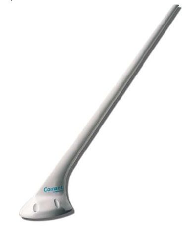
Comant CI-2480-200 GPS/VHF antenna (non WAAS) £525
Installation and sundries £3420
Additional items, which I free-issued to the installer, were:
1) KAC504 ARINC interface card
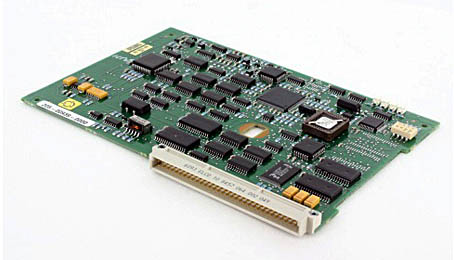
This (Honeywell P/N 071-00166-0411) plugs into the KMD550 MFD and provides
it with the ARINC 429 input capability required by the TAS605 system. This was
purchased from South East Aerospace
for $1150 (overhauled, with an 8130-3). A new one would have been $2500. There
is a fair number of these cards coming onto the used market because a lot of
people are removing the 1990s Honeywell/King avionics and installing "glass"
cockpits.
2) RG400 cable
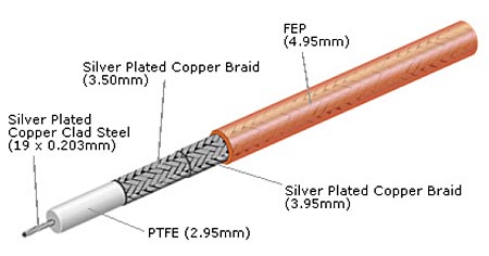
This double-shielded solid-PTFE coax is used for the four antenna cables and
is the best cable one can reasonably use. Most UK installers don't like to use
it because it is expensive, heavy and stiff. It was £6.64/metre and a
total of 25m were used. I bought a 50m reel and it's easy to sell the remainder
to freelance installers. There are several "RG400" fakes on the market
which have a very similar name but use a lighter and cheaper insulation and
their attenuation is worse.
A factor in the choice of a very well shielded cable is the apparent higher
incidence of burnouts of KFC225 autopilot
servos in aircraft which have a TCAS system installed. This sounds bizzare but
I now believe that the burnouts are caused by RF interference affecting the
KC225 autopilot computer and causing it to drive the servo(s) with a rapid waveform
which the servo cannot mechanically follow and which drives it into current
limit, which (due to a defective design of the servo) causes the servo to self-destruct.
Functionality
The operation of a TAS system is simple.
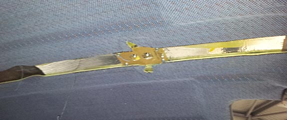
The system uses two antennae, as shown below, to get direction.
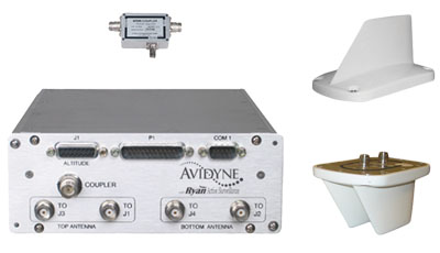
The upper one has two antennae within the single "blade" and the
relative power received by these two resolves azimuth front/back. The lower
one has two antennae which using the same principle resolve left/right. The
system does not use propagation delays to determine azimuth. The altitude resolution
is done by comparing your pressure altitude (obtained via a connection to your
altitude encoder) with the other aircraft's Mode C transponder return. The distance
is done by measuring the time delay between the interrogation and the target's
response.
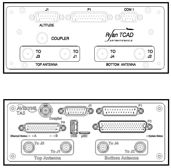
To avoid picking up transmissions of one's own transponder, a small "T-box"
coupler (shown above) is inserted into the transponder RF cable which picks
off the transponder transmission, and this is used to inhibit the TAS system
transmitting. A similar inhibiting function is done with the DME but modern
DME units have an output signal which is wired directly to the TAS system.
The information can be displayed on a variety of devices. Avidyne offer various
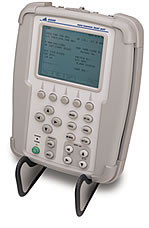
options, from dedicated units such as the ATD150
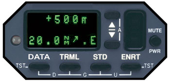
or the MHD300
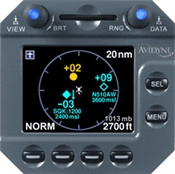
all the way through their glass-cockpit products such as this
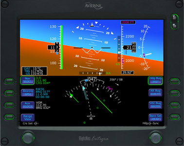
A number of 3rd party displays are also supported such as the Garmin GNS series,
and my KMD550 (if it has the KAC504 ARINC card fitted)
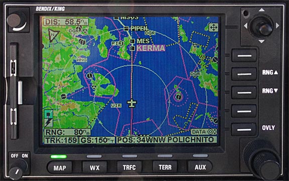
This is not stated in the manuals, but there are subtle variations in traffic
indication functionality between displays. The TAS605 unit transmits the traffic
data to all display units and each of those has its own configuration and can
choose to display data according to its own criteria e.g. one might show traffic
only 2500ft above and 5000ft below, while another might show traffic 5000ft
above and 5000ft below. Of course, it is also possible to disable traffic display
on a particular device!
Also, the TAS605 can output the traffic data in RS232 or ARINC429. These differ
in both the electrical interface and the protocol. The RS232 data includes the
target aircraft registration (as configured in the Mode S transponder) but the
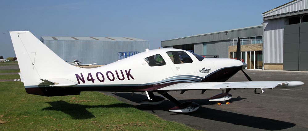
ARINC data doesn't. From what I saw on a flight with this system in this
Cessna 400, this feature shows the registrations only for N-reg targets
which suggests that the system generates the tail number by decoding the 24-bit
Mode S ID. Such decoding is algorithmically possible only for N-regs; other
countries have gone for a "random" mapping relationship. It would
be nice to see the tail number, even if only for N-regs, but the RS232 format
works only with Avidyne MFDs...
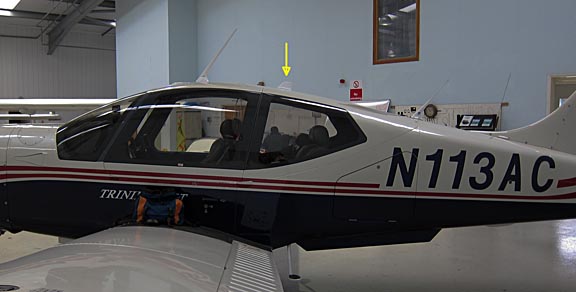
Installation
On a US-registered aircraft, unpressurised, the antennae are installed IAW
AC43-13 which is a generic aircraft repair/modification manual from the FAA.
The single-blade one goes on top and the dual-blade one goes on the bottom.
On the composite roof of a TB20GT, there are prescribed antenna locations which
have to be used. These are identified by removing the ceiling trim; the locations
are obvious.
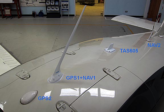
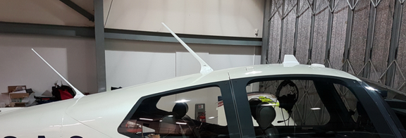
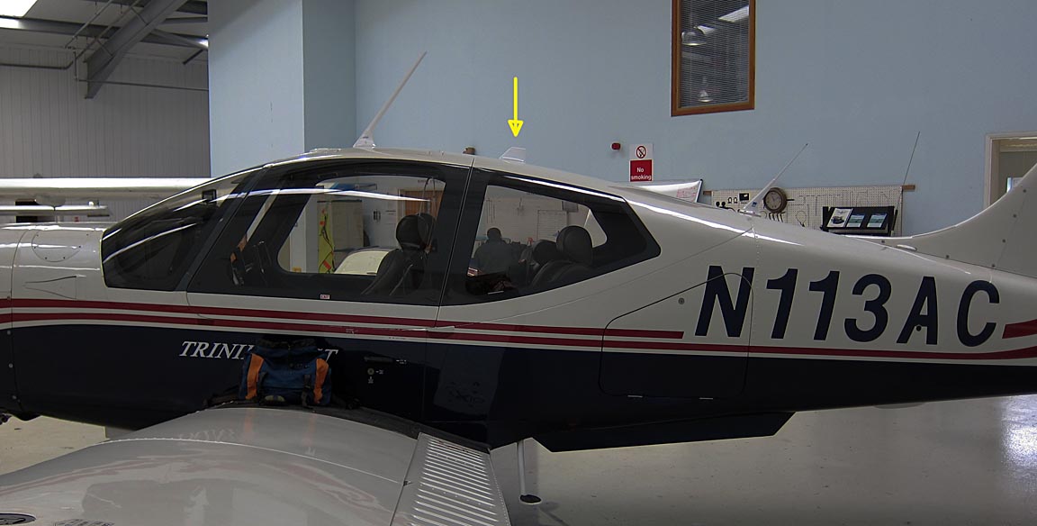
Antenna Location
I did a lot of "due diligence" on the antenna location, prior to
selecting the installer. The problem with TAS systems is that almost every well
equipped aircraft has so many antennae that it is impossible to comply with
the TAS manufacturer's requirements for minimum spacing to other antennae! The
wording is "avoid mounting either antenna within two feet of other
antennas, or physical obstructions (three feet for DME or transponder antennas)".
Obviously most systems are installed in breach of these requirements. Most work,
but some work better than others...
When my aircraft was new, in 2002, it looked like this
The single GPS antenna feeds the KLN94.
There were rather more antennae on the underside... transponder, DME, ADF.
Shortly after delivery, I had a 2nd GPS antenna fitted, which is at the very
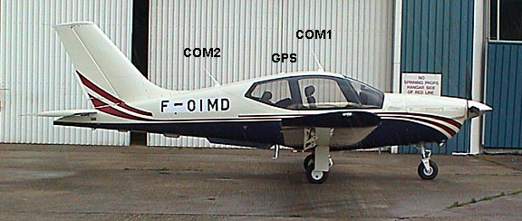
front of the roof as shown here, in front of the COM1 antenna
That antenna comes out on a BNC connector in the panel and is currently used
for a bluetooth GPS receiver.
That, I was told by the Socata dealer at the time, exhausted all available
antenna positions on the composite roof. The roof is about 20mm thick and antenna
locations are "scalloped out" i.e. the material thins out by about
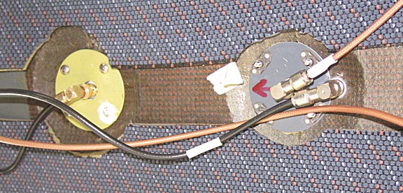
10mm. The following pic shows two of the locations provided; the one on the
right is a combined GPS+COM antenna
It is believed that fitting antennae elsewhere, into the full thickness of
the composite roof, would present additional difficulties because of the need
to mill away a lot of material from the top surface to reach the ground plane.
It has also been argued that AC43-13 would no longer cover it.
Later, once the ceiling trim was removed, it was discovered that the dealer
(who went bust several years ago) was wrong and another antenna location exists
which is in front of the COM2 antenna... but it was discovered too late to
make use of it. Moving the rear GPS antenna to it would have saved the cost
of the combined GPS+VHF antenna (see below). For future projects, it may be
useful for a GPS antenna, and/or a satellite phone antenna as described here.
In many TAS installations, these issues are solved by relocating one or more
VHF antennae to the underside of the aircraft, but that is more work
because the antenna cables should not have any connectors within them so would
need to be completely replaced, all the way to the instrument panel.
In this case, prior to the discovery of the extra antenna spot, it was decided
to remove the rear GPS antenna and replace the COM1 antenna with a combined
GPS+VHF antenna.
These combined antennae are a relatively recent introduction. They use an internal
resonant cavity notch filter to eliminate interference between the 11th or 13th
VHF harmonic and the 1575MHz GPS frequency which is a major problem - see notes
here.
They are not cheap. With the KLN94, I did not need the WAAS
version of this antenna, which would cost even more money.
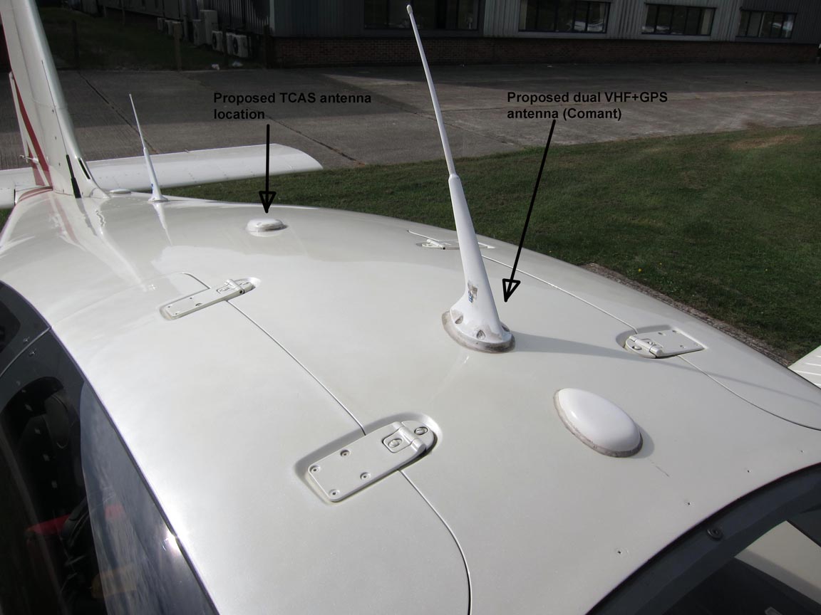
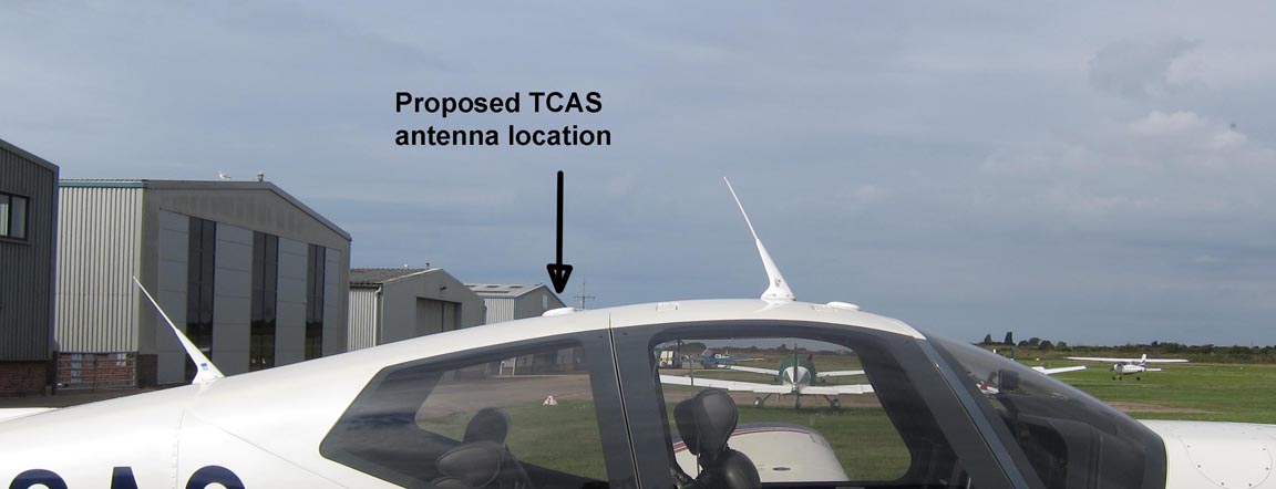
These pre-installation pics show the proposed locations
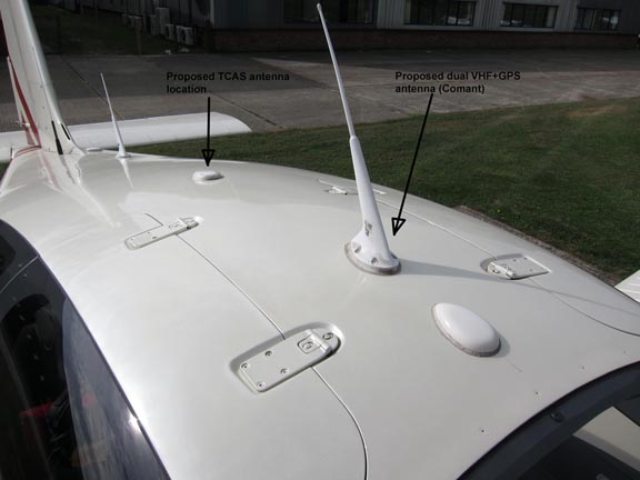
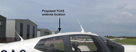
It can be seen that the proposed location lies behind a slight "curve"
in the roof which may affect performance in the forward direction. I sent these
pics to several US installers, Avidyne and their distributor DAC to check this
is OK, and to the limited extent that clear information could be extracted
by an "end user" the consensus was that it would be fine.
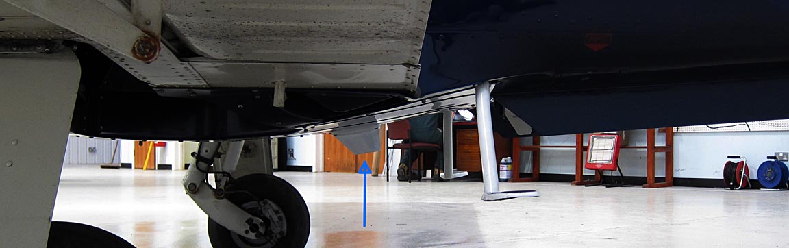
There was a similar issue on the underside where the bottom antenna would also
be behind a slight curve, being directly below the top one, and this was "OK"
also.
Ground Plane
The antennae need a ground plane as per the TAS605
Installation Manual. On the underside this is a non-issue because the belly
panels are metal. However, the TB20GT roof is a non-conductive composite which
contains a ground plane embedded within the composite material. This ground
plane is exposed at the prescribed antenna locations, so that the bases of antennae
mounted at those locations make a direct connection to it.
My earlier attempts to get a drawing from Socata showing the extent of their
ground plane were unsuccessful. I managed to get only these drawings 1
2. Their ground plane
is believed to run the whole length of the roof and its width is believed
to be the left-to-right distance between the door hinges, but the person who
supplied that information (on a US forum) works for Socata USA who are prohibited
from supporting European owners 
In retrospect it would have been easy to determine the extents of the Socata
ground plane, with a cheap (£100 or less) capacitance meter, with one
lead connected to the airframe and the other with a piece of metal foil on it
(say 50mm x 50mm) and by just moving the foil over the roof and seeing where
the capacitance suddenly changes. Or one could have used a cheap mains cable
detector from a DIY shop...
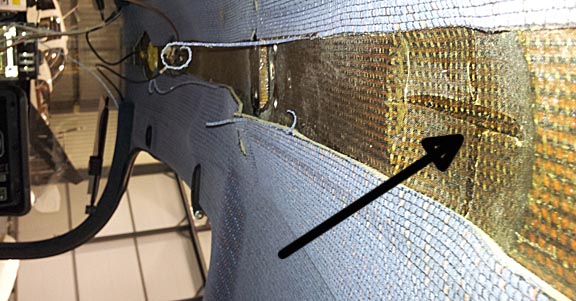
In what appears to be a misguided attempt to treat the composite roof as totally-composite
(no ground plane, as one might find on some aircraft types not certified for
IFR) the TCAS installer added another ground plane, about 20" wide, to
the underside of the composite roof, visible here as the silver colour
An extra ground plane is pointless because the existing embedded ground plane
will prevent the antenna "seeing" the new one...
The correct way of doing it means either (a) milling away the composite layer,
on the upper surface, all the way down to the metallic layer and mounting the
antenna directly on the metallic layer, or (b) counterboring the composite all
the way to the metallic layer and mounting the antenna on metal spacers whose
length is just right for the antenna to sit flush. I have not been able to establish
what exactly the installer did (subsequent correspondence was inconclusive)
but it appears no effort was made to connect to the internal layer. The end
result appears to be working, however, and the two ground planes will be only
a few mm apart, over an area of roughly 0.3 sq. metre, which will couple them
well enough through capacitance alone. I calculate the capacitance to be roughly
3000pF, based on a relative permittivity of fibreglass being about 5, which
is plenty enough at the GHz frequencies involved. Both ground planes are connected
to the airframe, with a low resistance, but that is via wired connections which
won't do anything for RF.
For the best job, the antenna bases should be sealed with PR1422
which is a much higher grade sealant than the white silicone normally used.
Other Installation Issues
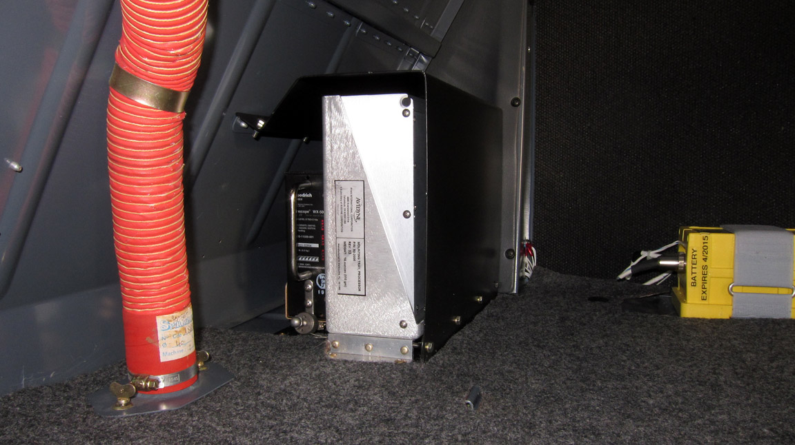
The TAS605 box itself normally goes into the luggage compartment. In this case
it ended up next to the WX500 stormscope box (the WX500 is the smaller unit
with the chrome handle)

The black metal cover was fabricated by the installer and is merely an enlarged
version of the one which originally covered the stormscope box.
One could mount the TAS605 in the void behind the luggage compartment but that
would require some metalwork because there is no mounting surface there, and
it would be subjected to a much wider temperature and humidity range. The lowest
specified temperature is -20C and this could be easily exceeded in high altitude
flight.
Due to the KFC225 factor (mentioned earlier) I made sure the two belly panels
were properly grounded to the airframe. They are aluminium and are held down
by many screws, but they are painted and there is no guarantee that there will
be a connection. The TAS605 installer fitted one grounding wire (on which they
stripped the thread on the stud so badly we had to grind off the nut at the
subsequent Annual )
and a second ground strap was fitted later during the Annual. The lower TCAS
antenna is mounted on the belly panel (which acts as a ground plane for it)
and if the belly panel is not thoroughly grounded to the airframe, it will be
radiating heavily into the airframe and the RF will be picked up by all the
wiring inside the aircraft.
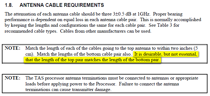
The TAS605 installation has some weird antenna cabling requirements:
All four antenna cables must be at least 5m long. The actual wording is "the
attenuation of each antenna cable should be three 3±0.5 dB at 1GHz"
and together with RG400 attenuation being
0.6db/m this gives the 5m minimum length. With more exotic cables such as this,
the minimum length will be even greater. Moreover, the two top antenna coax
cables must be the same length, and the two bottom antenna cables must be the
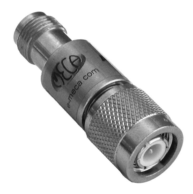
same length. The tolerance on "same" is 5cm. Where there would be
a lot of spare cable, attenuators (example) can
be used but they are fairly pricey, and very pricey if bought from "aviation"
sources. In most light GA installations there will be a lot of spare cable (but
not enough to justify attenuators plus the extra connectors) and the simplest
solution is to coil it up somewhere. In the TB20, the best place is to locate
the coils in the void behind the luggage compartment
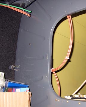
The antenna cable is the brown cable in the above pic, shown before it was
relocated on my request to not protrude into the access hatch (see later notes
on Installer Performance).
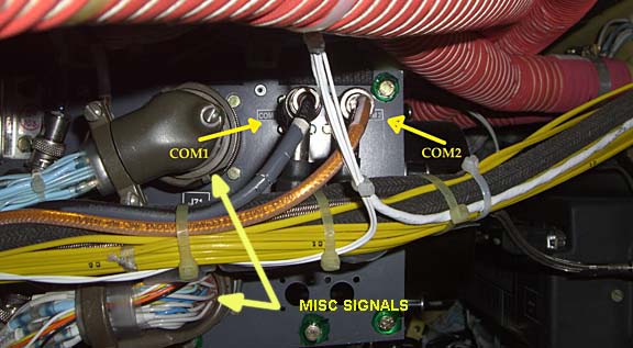
Connections to Other Avionics
There are some connections between the TAS605 and the rest of the aircraft:
Pressure altitude input. There are at least 2 ways to do this:
ARINC 429 from the Garmin GTX330 ARINC output, or connecting up to all 10 of
the gray code wires which go from the altitude encoder (a KEA130A encoding altimeter
in my case) to the GTX330 (GTX330
IM). The former method is much neater, but there is a mysterious incompatibility
which neither Avidyne nor Garmin wish to sort out. So the gray code connection
had to be wired up...
Heading input. This can be done in several ways and in my
case I was able to use the SN3500 EHSI's ARINC output, which provides this (Label
320) and unfortunately very little else. There is a missed opportunity for Sandel
to enhance the SN3500 as an ARINC data concentrator and re-output all the data
it has connected to it.
Traffic data output. In this aircraft this goes to two display
devices: the KMD550 MFD, and the SN3500 EHSI.
The KMD550 needs the KAC504 ARINC card which is installed using the instructions
in the KMD550 Installation Manual.
All configuration is via the front panel; no laptop etc is needed.
The KMD550 needs firmware version 01/03 which is actually very old (2001 or
2003?). The KMD550 database cartridge, which can be purchased as a one-off update
from Honeywell, also updates the KMD550 firmware. A one-off update is $285 for
an exchange flash card (2012 pricing) which did not
stop one pilot in Germany being quoted €1000 for it by a very well known
avionics shop Because
the KMD550 database is non-critical (basically land/sea outlines, airports,
navaids and airspace) and all flight-specific data comes from the GPS, many
pilots update the KMD550 database relatively infrequently. At present (1/2013)
Honeywell still support the KMD550 with database cards, even though software
development on it ended some 10 years ago. If Honeywell stopped supporting the
KMD550 with database cards, and your KMD550's firmware was too old for the TCAS
requirements, somebody else's database card could be copied to the older one
using the CSM OmniDrive USB2.0 Linear
Flash writer from CSM.
Unlike the database copy protection schemes used in most IFR GPSs, the KMD550
database is not locked to the particular KMD550, or to the FLASH card.
The SN3500 does not need any hardware changes but does need a "Traffic
Enable" software key, which Sandel sell for nearly $1000... This key is
obtained from Sandel, by supplying them with your EHSI serial number. I decided
this feature was worth having because it provides a second means of displaying
the traffic data.
Ground mode sensing. The TAS605 has a "ground mode"
in which traffic is displayed (which is very nice e.g. you can see any
transponding traffic on the final approach before you enter the runway) but
audio warnings are disabled. There are several ways to do the ground mode sensing.
One can wire to the landing gear squat switches, or one can install a differential
pressure switch which activates when the pitot pressure exceeds the static pressure
by a certain amount. I had the latter; the switch is a type widely used on Cirrus
aircraft, P/N 14128-001 which is one of these,
P/N visible here:
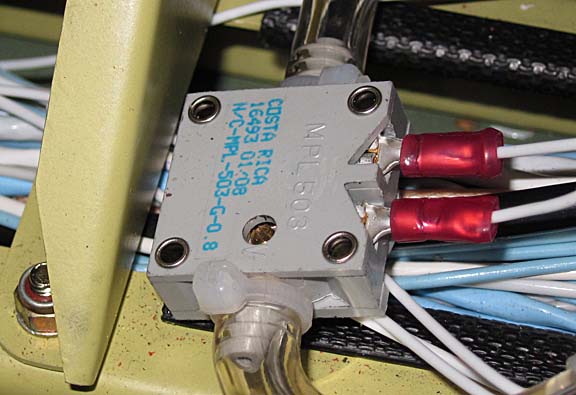
The same pressure switch was used to switch both the TAS605 and the GTX330.
The use of a single switch to do both requires the use of two diodes
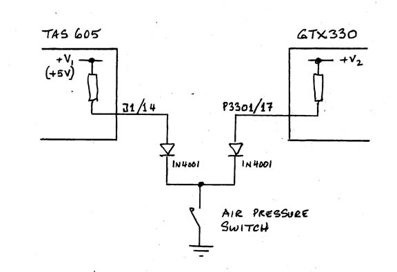
to guard against current flow from one instrument to the other, under fault
conditions.
Audio output. This needs to go to an unswitched intercom input,
so it cannot be pilot-disabled. In my case there were no unswitched inputs left
on the PMA7000 intercom, so the TAS605 was connected to an input pin (Unswitched
Input #2) which was shared with the KFC225 autopilot.
To ensure that both sources drove the intercom input properly, a 470R resistor
was added in series with the TAS605 output, to match the 500 ohm output resistance
of the KC225. Because the KFC225 annunciations are very loud, I fly with all
headset volume controls set to MIN, and use the various radio controls to adjust
the volume as required. The TAS605 output level thus had to be adjusted upwards,
to match the current KFC225 volume, which is done with a laptop connection.
Socata documentation practices mean there is a question mark about the availability
of the two unswitched inputs. This diagram shows what
is supposed to be in the aircraft, but there are at least two very similar diagrams
covering the late-GT version (i.e. with the KFC225 autopilot referenced). Despite
selling the TB20GTs for about £200k, Socata never produced an airframe-specific
set of wiring diagrams, so an installer has to examine the existing wiring to
see which diagram is a "best match". So, it may well be that Unswitched
Input #1 was available after all.
Mute/Test switch: a small momentary switch is installed which enables
the TAS605 to be momentarily muted. If pressed twice, it generates a "ground
mode" annunciation.
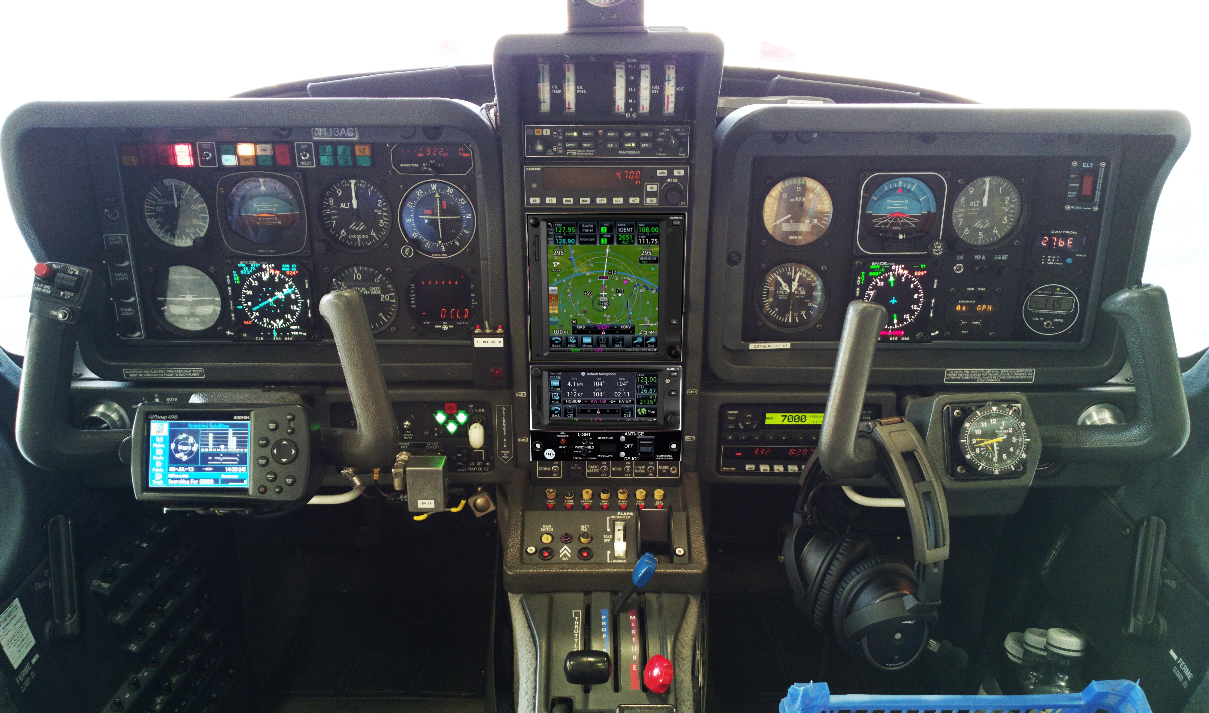
The TAS605 installation was planned to be carried out without extracting the
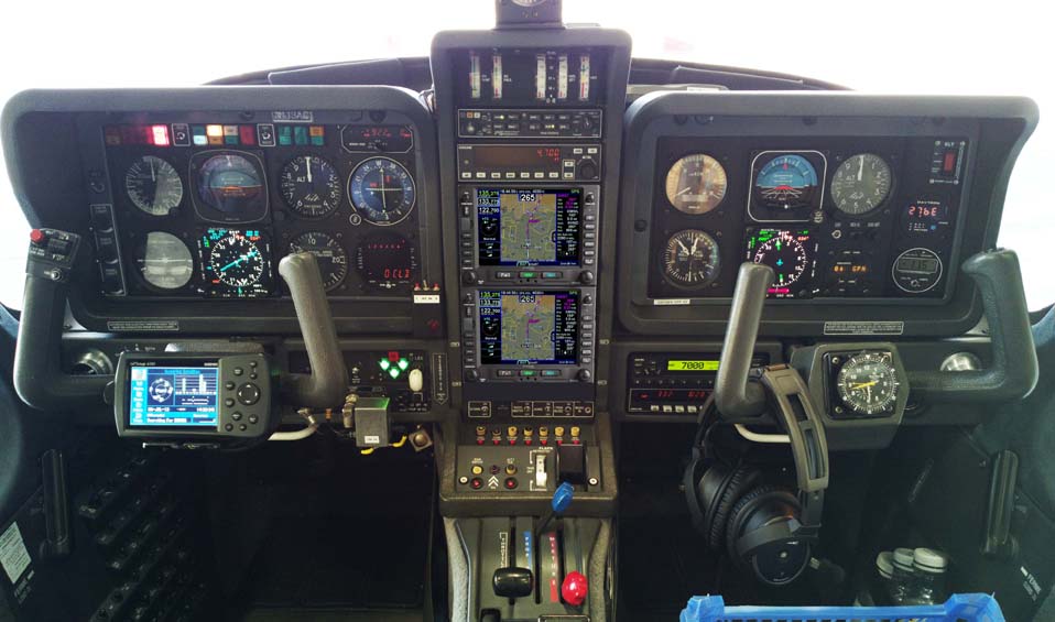
TB20GT centre avionics stack, shown in the centre here
Removing the centre stack takes about 1 hour if you know exactly how to do
it, and if no previous installer has run any cables directly in/out of it. Various
connectors and unused connector locations are provided for such cabling
but since the backs of these are inaccessible until the whole stack is removed
and stripped down on a bench, most installers just run cables straight through
the various holes and leave a problem for the next one... It is OK to run cables
like that provided the installer puts in an inline connector!
One can access the intercom without removing the centre stack, because it is
at the very top and just removing the grey trim gives access to the connectors
on the back of it. One can also access the KMD550 connections, by pulling out
the KMD550 and loosening its connector backplate; the KMD550 hole is big enough
to get a hand through.
Overall, I would rate the wiring difficulty in this installation at the "easy"
level and the wiring is about 2 days' work. Installing the two antennae, with
all the interior trim removal and refitting etc, could take about a week, and
attention must be paid to the required ground plane areas. So 2 weeks for the
whole job is a reasonable estimate, for 1 person doing it.
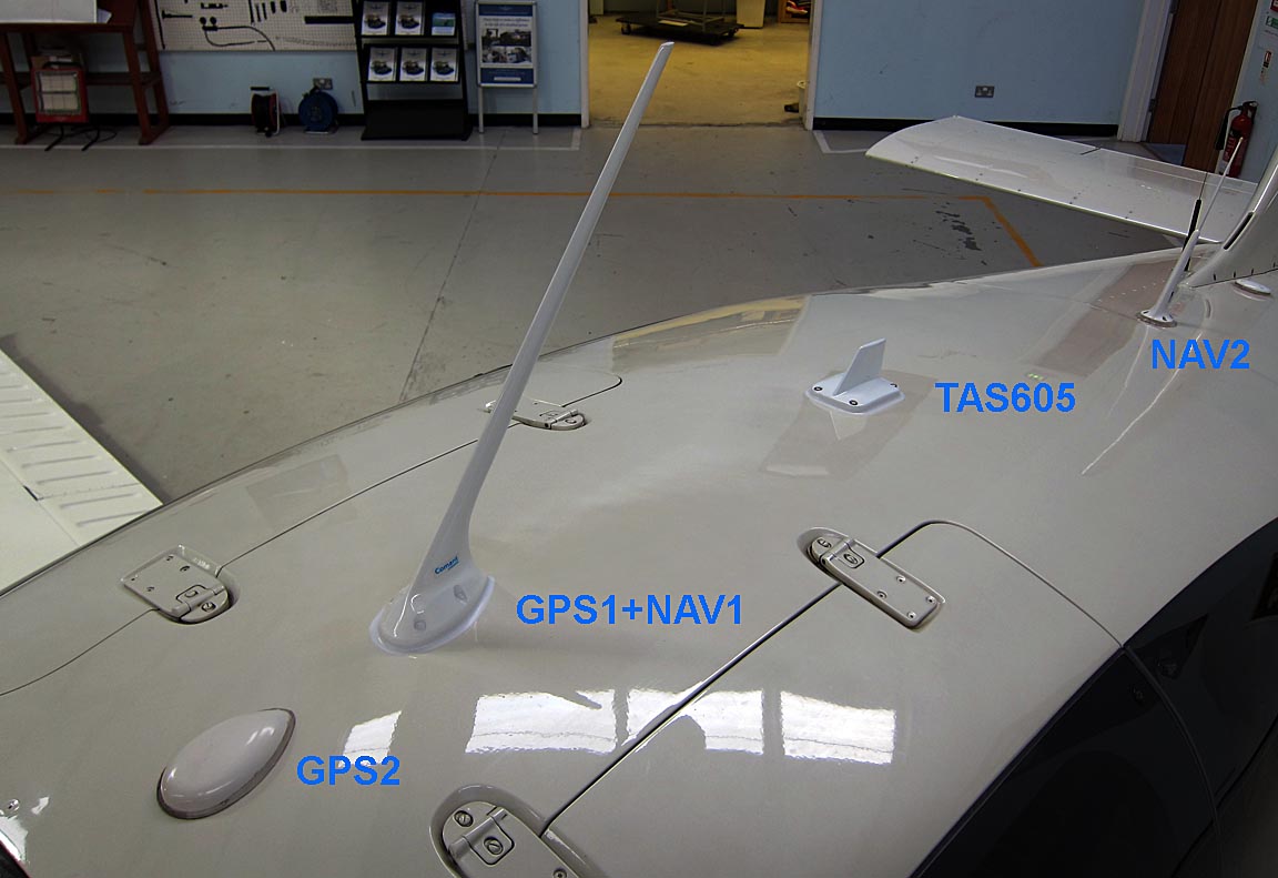
The final antenna locations are here; top
Side view:
Underside:

The lower antenna is roughly 200mm more forward than the upper antenna, which
does not matter at all.
Installer Performance
I do a lot of long trips in the aircraft and thus
I am very fussy about who works on it, and I personally inspect all work done.
This installer was carefully selected, based on good reports from customers
I knew. The price was not haggled over, and the price paid was a "top price"
for a supposedly high quality job.
The installer did it on time - just over 2 weeks.
Unfortunately their workmanship was poor. The list is long and every subsequent
opportunity to work on the aircraft - an Annual service was done shortly afterwards
- turned up more bodges. I quickly lost any confidence in the work and decided
to do a very thorough inspection, which included paying a freelance avionics
man to check stuff while he was doing other (unrelated) work on the aircraft.
A lot of the wiring was untidy, with one wire cable-tied to the emergency gear
release cable sheath, coax cables running across the hatch that leads into the
rear of the aircraft, etc. But that's just cosmetic...
Minor damage was done to trims, and a number of screws turned out to be stripped.
A heater hose attachment was broken right off and together with the hose no
longer secured with the original cable ties, the hose was close to fouling control
linkages. Another heater hose was damaged and will need to have a section replaced.
On the initial delivery, I found that the autopilot audio annunciations no
longer worked, due to incorrect wiring to the intercom (the 470R resistor was
required in series with the TAS605 audio output). Also the GTX330 GND/AIR auto
switching didn't work, due to the wire to the GTX330 being missing altogether.
I requested a "radio check" to make sure the basic navaids and the
autopilot still worked, but this was not possible because the company had no
LOC+GS test set (the Sandel SN3500 EHSI will not display a glideslope if there
is no localiser signal, so one needs a test set which generates the full ILS
signal, such as an IFR4000) and their VOR tester worked
only intermittently. I arranged for a radio check to be done later with a freelance
avionics man, and all navaid reception (and autopilot tracking of them) was
later verified in-flight in VMC conditions.
On taxi out, the instrument backlighting was found to be not working. This
turned out to be a short between one of the instrument light wires and "somewhere"
so they just re-ran that wire and cut the original off at both ends and left
it in the wiring harness! This is obviously totally unacceptable (anything like
that is a fire hazard) so at the Annual a few weeks later the wire was traced
and pulled out (took only about 10 minutes) and found to be undamaged, so the
short must have been in one of the pieces they cut off.
After I discovered the first batch of bodges I flew the aircraft back to them
and left it there for a number of days to fix the various issues and even on
the final collection I immediately found yet another bodge: the circuit breaker
panel was not screwed back in place and 3 screws were missing from it.
However, potentially life-threatening stuff was discovered during the subsequent
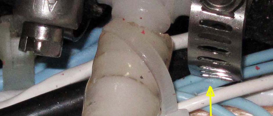
Annual. This video
shows one of the air pressure switch hoses was barely attached and came straight
off. If this happened in flight, it would have connected both the pitot and
static lines to the cockpit pressure which would have been "interesting"
in the TB20. It would have been much more "interesting" in a pressurised
aircraft which this company often works on, with the resulting loss of airspeed,
altitude, and many aircraft systems such as the autopilot and the capability
to fly any instrument approach that uses baro assisted VNAV.
These videos 1 2
show the wiring harness (where the gray code wires were taken off the back of
the GTX330) is fouling on the control linkage. This was not obvious on my early
checks and is clearly visible only by inspecting with a mirror, or when the
RH instrument cluster is tilted forward.
This video shows another
aspect of the same thing where a sharp edge of the control linkage is
rubbing on the underside of the harness.
This pic shows a sharp edge of a jubilee clip cutting
into wire insulation. There is already a dent there and eventually it would
have cut through.
Later, it was noticed that the centre avionics stack was showing severe vibration.
It turned out that the trim which goes over the top and down the sides and on
top of which the vertical card compass is fitted, was forced back on. It was
jammed between the stack metalwork and the windscreen, with the compass touching
the winscreen material! The windscreen gets a lot of vibration from the propeller
slipstream and this was being transmitted down via the compass. It took about
30 mins to fix it, and it turned out that the bodger who refitted the trim left
some inline connectors trapped underneath it, which should have been tucked
away into some cavities.
Much later, when upgrading the unit to the TAS605A, it was discovered that the whole unit was mounted backwards, so the mounting tray was useless for sliding out the unit. One had to unscrew the mounting tray the get the unit out.
Obviously the whole job was done in a mad rush.
The company is one of UK's biggest, has a good reputation from the past, has
EASA Part 145, EASA Part 21, FAA Repair Station status, but obviously I cannot
recommend them on the basis of my experience. Their attitude in attending to
the issues has been positive but even after their attention was drawn forcefully
to the lousy work they seemed to be unable to deliver either reasonable workmanship
in fixing it or exercise any form of quality control. Eventually the various
known defects were fixed and the aircraft was thoroughly inspected by myself
and others, but I am not going anywhere near them again.
Operation
The system works well and is accurate in relative altitude, distance and azimuth.
Distance appears accurate. There is an easy way to verify it: as you approach
an airport, you can see aircraft on the ground, at the expected altitude, if
they have their transponders on.
Relative altitude is hard to verify but traffic acquired visually appears accurately
depicted, and one can use the same trick as above with targets on the ground
whose altitude is known.
The azimuth is easy to verify with visually acquired traffic which appears
generally accurate to within about 10-20 degrees. One can also check it by flying
near a big airport (outside controlled airspace) and seeing the traffic lined
up on its ILS.
Within this 10-20 degree azimuth band, targets do sometimes wonder about, and
an occassional sudden change in the azimuth of say 10 degrees makes them look
like they have suddenly turned into an SR71
One limitation of the system is that it sometimes cannot see traffic
which lies in a cone above the aircraft, or in a cone below the aircraft. These
are potential blind spots. It's hard to say how big the cone is but a 30 degree
included angle is about right.
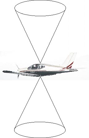
This appears to be caused by such targets not being seen by both antennae
(due to airframe masking of one antenna or the other) and the TAS605 suppresses
such returns. This should not be a problem in practice unless somebody descends
into you while remaining directly above you the whole time, or climbs up into
you similarly. It's most likely to be noticed when joining a circuit from above,
when targets vanish as they pass below you.
Targets approaching the above cone are more likely to suffer from azimuth errors,
before/after their disappearance/reappearance.
The system works impressively well on the ground too, picking up both ground
based and airborne targets, but the azimuth is likely to be way off if there
are any metal building nearby - due to reflections from the buildings.
The claimed 13nm range is difficult to test because so much depends on the
transponder power of the target, but in reality anything over about 5nm is beyond
visual acquisition (for light GA aircraft) except under the most favourable
circumstances e.g. at night, landing lights on, head-on, and with nothing illuminated
on the ground. And at 5nm the TAS605 appears solid.
For its intended purpose (avoidance of conflicting traffic) the TAS605 system
appears very good. For example, traffic within a +/- 1000ft vertical range
and a few miles away, and approaching, is depicted in a stable way which facilitates
visual contact acquisition. The fact that a visual contact is rarely acquired
in practice is just something which makes one feel the money was well spent
As mentioned above, the TAS605 transmits (via ARINC 429) all data it
has to all display devices. Each device can then select its own scaling
or its own vertical limits on the displayed traffic. I found that the only way
to get the KMD550 to display the same as the SN3500 is to select "normal"
on the KMD550. I found the best setting for the SN3500 is "ON"; additional
information is in the Traffic section of its
POH. Sending "everything everywhere" is also how the WX500 stormscope
data distribution works, and is very good because if one display device failed,
the other remains fully available.
Here is a video (25MB)
which shows the end result, in flight, and on the ground. The comment about
"non transponding" traffic actually refers to non-Mode-C traffic on
which no altitude is indicated. Totally-non-transponding traffic is obviously
invisible to the system.
Apart from selecting the options on the display devices, there is no "user
interface" to speak of. The system has no on/off switch, it comes on with
the avionics master switch, and the default settings of the display devices
are fine.
The Pilot's Operating Handbook for the TAS605 is a
very generic document which talks a lot about Avidyne's own traffic display
devices and contains little other useful information, so it is just as well
that the operation of the system is very simple. It's more important to read
the Traffic sections in manuals of the display devices.
Paperwork - US Registered Aircraft
As stated earlier, the TAS605 is covered by the AML STC and the extras (antenna
mounting etc) are done IAW AC43-13.
The STC also comes with an FAA approved AFMS (Flight Manual Supplement) which
is a legal requirement to have in the aircraft flight manual (AFM). You print
this off to the required size, punch the holes down the edge, and insert it
into your AFM. The AFMS is so generic as to be almost useless but it is a legal
requirement.
Any Major Alteration needs a 337. If the 337 is supported by an STC, it is
sent directly to the FAA in Oklahoma for filing. This is not a Field Approval
so the FAA does not need to pre-approve the job. After the work is completed,
the installation is checked for conformity to the 337 by either an A&P/IA
or by an FAA Part 145 Repair Station, the 337 is signed and sent off to the
FAA.
A W&B sheet was also drawn up by the installer. The complete system, including
cabling, weighs only about 6kg.
Paperwork - EASA Registered Aircraft
Many TAS600-series systems have been installed on G-reg TB20s.
According to some UK installers, approval on an EASA-reg aircraft is via a
Minor Mod. The AFMS is approved under an EASA Form 36. The minor change
cost will depend on whether the avionics shop already has some prior similar
approvals, but if generated from scratch, should cost £900-£1200.
The Form 36 approval for the AFMS costs about €260.
The Avidyne TAS system already has an approval on all Part 23 single-engined
aircraft via a German LBA validation of an FAA STC, so no additional design
and certification fees are applicable.
Paradoxically, therefore, EASA treats the system as a Minor mod whereas the
FAA treats it as a Major mod... but in practice the FAA route is much simplified
by the AML STC.
A quick google digs out numerous approvals for various aircraft types. For
example it suggests that the UK CAA appears to have approved a TAS600 system
at some stage in the past, under # LA101077, as found about halfway down here.
EASA is required to accept any such prior approvals.
Update 8/2013: I found a note from Avidyne from 2007 stating the TAS600
range is covered by the same UK CAA Aircraft Equipment Approval" as the
old Ryan 900BX. The approval number is stated as "LA101077" which
oddly enough is the same as above...
2+ years later (July 2015)
The system has been working well and both myself and any passengers think the
money has been very well spent - when flying around in Class G airspace especially
in the UK at weekends. One still finds a good number of Mode A targets (no altitude)
which I think is very socially irresponsible because it denies visibility of
altitude to ATC too.
The only issue is that head-on traffic at same or similar altitude is reported
quite late. There is a partial blind spot on the straight-ahead bearing, and
often such traffic doesn't appear till it is just 1 mile or so away. However,
often it does appear at say 5 miles before than and then disappears! This isn't
consistent so is probably related to the quality and power of the target's transponder
installation. 1 mile is enough at GA speeds and much better than nothing. I
wonder if this is due to propeller shielding?
With maximum distance, there is a strong correlation between light GA traffic
and jets. Obviously, the quality of transponder installations varies a lot.
The 15nm figure for the TAS605 is a software limit; the actual distance is much
less and varies between 5nm and 10nm for light GA.
Update January 2019
I had an opportunity to revisit the compromised range issue, and based on e.g. this the location of the upper antenna was suspected.
Because the original installer had to make all four coax cables the same length, there was plenty of spare length going to the upper antenna to enable it to be moved forward on the roof - about 60cm in this case. The combined GPS+VHF antenna was then moved to the old TAS antenna location; this was also not difficult because one of the two cables was long enough and the other was extended with a short BNC extension cable made up with the proper RG400 cable.
This is the end result
Flight tests immediately showed a dramatic improvement in the range all around, especially at 12 o'clock where I now get airliners up to the full 15nm range and GA targets to around 10nm.
The mechanicals of the antenna installations on the TB GT composite roof are not trivial. The antennae are all mounted in the scalloped-out locations, and these are OK for normal antennae, but the TAS antennae are slightly too big (in length) for all four screws to fit inside the scalloped-out circles. And one cannot just use longer screws, because tightening the nuts crushes the honeycomb composite. So one has to use spacers, around 13mm long, and these prevent the composite being crushed. The length of the spacers needs to be just right so tightening the screws squeezes the composite just a little. The doubler plate (supplied in the TAS kit) works fine with this. The previous installer did some bodges there but on this occassion proper brass spacers, 8mm OD and ~5.5mm ID for the screws, were machined. The TB GT roof is a hard composite of about 3mm and then about 11mm of honeycomb, except in the scalloped-out areas where you have just the 3mm hard material.
The next issue was the ground plane which every antenna (of the types used here) requires. The original TAS installer stuck some conductive tape to the underside of the roof; this probably works well enough. However, when that TAS antenna was moved to its more forward location, the grounding had to be checked. A standard electrician's metal detector immediately established that the whole roof has a metal layer in it, but it was not obvious how to connect to it because - looking in the various holes - it was obviously very thin. Fortunately the new forward location contained an exposed metal surface there which connected to the airframe. It is a mystery why Socata provided that in the forward location and nowhere else, despite providing several antenna locations.
Note also that Avidyne revised their installation manual, with this new requirement which represents a useful concession over the old one where all four had to be the same length.
Update April 2019
Time to look at ADS-B... This is not mandatory in Europe under any circumstances for light GA. There is a proposal for > 250kt or > 5700kg. It would be good to pick up more traffic, because a lot of light GA flies incognito for various reasons (most of them not exactly honourable). I remain to be convinced that those who turn off their transponder are any more likely to be radiating ADS-B OUT (which is actually technically much easier to monitor from a great distance away) but at the right price I would like to look at it.
Avidyne have finally brought out the long-promised ADS-B IN upgrade for the TAS605: the TAS605A.
This needs a WAAS GPS position input. This can be via RS232 (the Garmin "WAAS GPS" data stream, which is secret alsthough they do license it to other avionics firms under an NDA) or via ARINC429 (which is an open protocol and in this case there is no "funny business" although there are very few ways to obtain GPS position in this way). Currently I have only the KLN94 (which is non WAAS) and due to the dire situation with avionics installers (read this article under Installer Performance!) I have little appetite for the large avionics job which upgrading to 2x IFD540 or GTN650+GTN750 (the two configurations which would make sense in my aircraft; the foregoing pics are photoshopped) would involve. So I considered installing a GTX335/345 which would provide the WAAS GPS source and would also do ADS-B OUT. However widespread enquiries have not yielded any confirmation on whether this is compatible, even though it "should be". Avidyne are pretty clear it will be fine, for both the GPS input and for driving my three display devices, and the TAS605A IM later version says so too. However I know enough about the avionics business to know that if it is installed and doesn't work, I will be left hanging. Garmin is a bigger risk than Avidyne because Garmin will not communicate on any real detail.
The TAS605A upgrade can be sidestepped because there is a Garmin box - GTX345 - which can combine the ex-TAS605
ARINC429 traffic data stream with the traffic data stream from a Garmin ADS-B
receiver and feed the combined data to the display device. However, it is impossible to get assurance that this data stream will work with my existing display devices...
Also there is an unsolved question whether the TAS605A will see only certified ADS-B OUT emitters (SIL=3) or some of the uncertified ones (SIL=0-2) so it won't see any of the countless brands of portable/handheld ADS-B gadgets which are on the market.
Update February 2020
Another TB20 owner has installed the L3 Lynx NGT9000 system. He kindly wrote it up on EuroGA here. This is probably the best product to go for today. It does not require the large box is the back of the aircraft; everything is contained within the single transponder-sized unit in the panel which also displays the traffic. What the compatibility of it is with my old avionics I don't know, however.
Update January 2025 - TAS605 to TAS605A Upgrade
This EuroGA thread is relevant.
The decision was finally made to upgrade the TAS605 to a TAS605A which also supports ADS-B IN, and merges any targets which are seen in both the old TAS mode and as ADS-B. Information posted in this thread (partly from Avidyne) suggests that everything from SIL=0 upwards may well be displayed, if the display devices (the 2 x SN3500 and the KMD550) do not block it. Such blocking seemed unlikely since the data is sent over ARINC429 which doesn't support SIL or SDA number transfer. It is also established that Garmin display devices, connected over RS232, do block this traffic!
A big part of the reason to finally go for this upgrade was the availability of a commercial and cheap C programmable ARINC429 data converter, so if there was a data stream compatibility issue, this could be used to "fix it up". In the end, this was not needed. The "605A" data was exactly the same as the "605" data. Another reason was Avidyne's statement that they don't suppress SIL=0 or SIL=1 data, so if you are feeding display device(s) via ARINC429 (not RS232) you should see the various uncertified emitters; this is a huge plus.
Due to my 10 years' hesitation, the cost was now much higher. The man at Avidyne UK who offered me an upgrade for $2000 had recently retired and Avidyne refused to honour his offer. The best I could get was an exchange via a contact in the US, for $7500. It is almost possible to get a new TAS605A outright for this amount so this is actually quite expensive and worth doing only if the old box is almost worthless, but I reckoned that it may well be worthless since not a single example is listed on Ebay, including US Ebay.
Comparing the installation manual for differences suggests that the "A" is plug-compatible with the non-A, although the "A" manual section does not actually say that. Avidyne confirmed that the "A" is in fact plug-compatible. Avidyne have added a huge 78-way connector, most of which is unused, but it duplicates some of the signals on the other connectors so you need to be careful to not get conflicts. For example if the original installations feeds in ARINC429 heading on ARINC429 #1 input, on one old connector, you obviously cannot use ARINC429 #1 input on the other connector! This shows the old and the new:
COM1 - the "laptop config" connector - is gone and instead you use some of the RS232 ports on P2. Old J1 is new J1. Old P1 is new P1. P2 is the new one but very few of the 78 pins need to be connected; the most obvious is the GPS position input which ADS-B IN requires (RS232 or ARINC429). On the GPS position, with ARINC429 it was established experimentally that these packets are sufficient for the GPS position, but ultimately RS232 from a certified Garmin source was used.
The mounting tray is the same. The five RF connectors go into more or less the same places.
This fun writeup shows the internals of the old TAS605, and unfortunately shows that the metalwork quality of the new TAS605A is rather poor.
There are some other details which are useful. The TAS605A can received mixed-speed ARINC429 so e.g. the heading data can be slow (12.5k) and some other data (e.g. an ARINC429 GPS source) can be fast (100k). On the old TAS605 all had to be the same speed. The TAS605A uses dynamically assigned ports which seems to work although getting the laptop connection to work (repeatedly pressing RETURN and typing CONNECT until you get a > prompt) sometimes takes a long time because the unit is using the same port to transmit various binary data strings. The laptop config should be needed only to enter the aircraft Mode S hex code (for ADS-B IN to work) but it gives you access to various debugs.
The upgraded unit works very well. TAS operation is just like before, with a 15nm radius (most likely limited by software), and the ADS-B operation works with a 25nm radius. This difference appears to be undocumented but is obviously welcome!
One can pretty well tell which aircraft are emitting ADS-B because their tracks are much more steady, whereas TAS-derived tracks tend to be "jumpy".
The remaining test is whether a Sky Echo 2 (configured for SDA=0 or SDA=1) is visible on this system. It is visible - see here. This is a major gain because a lot more traffic now shows up. Especially in the UK where the CAA's crazy "bust them all" pilot persecution policy means that around half of GA traffic flies with transponders either turned off or set to Mode A only.
It appears that the UK version of the Sky Echo 2 is fixed to output SIL=1, whether SDA is set to 0 or 1. However, certified traffic systems are supposed to reject SDA=0 traffic, and the TAS605A does not, which is much more useful. Avidyne did confirm this is the case and they select/reject only on the basis of the fix accuracy.
That test also showed that the Sky Echo 2 is an unreliable ADS-B emitter. Its GPS tends to be marginal, losing fix during turns, and take a long time (or for ever) to gain a fix if turned on while airborne. The LED indicators for GPS and ADS-B are basically worthless. It may be a reliable receiver for ADS-B, FLARM, etc, but even that won't work well of its GPS is poor, because ADS-B IN requires a GPS position input.
Would I do it again?
Because of the hassle I got with a supposedly top-class company certified for
every imaginable type of aviation maintenance, I am tempted to say NO. But it
does work well, does not clutter the aircraft (is virtually invisible) and has
a negligible W&B cost.
However, if I was doing it again, I would rent a hangar for a couple of weeks
and pay a good freelancer to install it (closely monitored, obviously) saving
a few k in the process. However most owners don't have the expertise to design
and manage such a project, and actually neither do most freelance installers
whose bread and butter is avionics repair or screwing in the occassional GNS430
or similar. It may also be difficult or impossible to do such a closely managed
job on an EASA-reg (Part M) aircraft; owners of those have no choice
but to trust the company approvals, which can evidently be a trust totally misplaced...
How well does it work?
The system has been working very well, and really drives home
how much traffic is never seen. It doesn't matter how many people you have on
board, all knowing roughly where to look, but they cannot see the target aircraft.
At least 90% of traffic is never spotted.
But equally one is often in a situation where one has spotted something and
then lost visual contact with it. The TCAS system is likely (if the target has
Mode C/S) to show it in a way which enables one to not worry about it. This
is also a great benefit. However, obviously, there could be more than one plane
out there and the one you briefly spotted was the non-transponding one
Flying around Europe IFR (example) one sees
virtually nothing on the TCAS, if the range is set for 3000ft above and below.
The separation between light GA and jets in controlled airspace is normally
so great that nothing shows up even when overflying major airports like Frankfurt
or Schiphol.
The system also really earns its keep in Class G, especially in the
UK. I used to think that traffic display products are useless in the circuit pattern but this is very incorrect. There is often traffic which even ATC don;t know about. I have often departed the circuit, or gone around on a final approach, based on the TCAS data showing me somebody very close.
All avionics manuals here were found freely on the internet.
Last edited 13th May 2025
Any feedback, reports of dead links, corrections or suggestions much appreciated
Contact details
Aviation Home
