Sandel SN3500 EHSI Installation in a Socata TB20GT
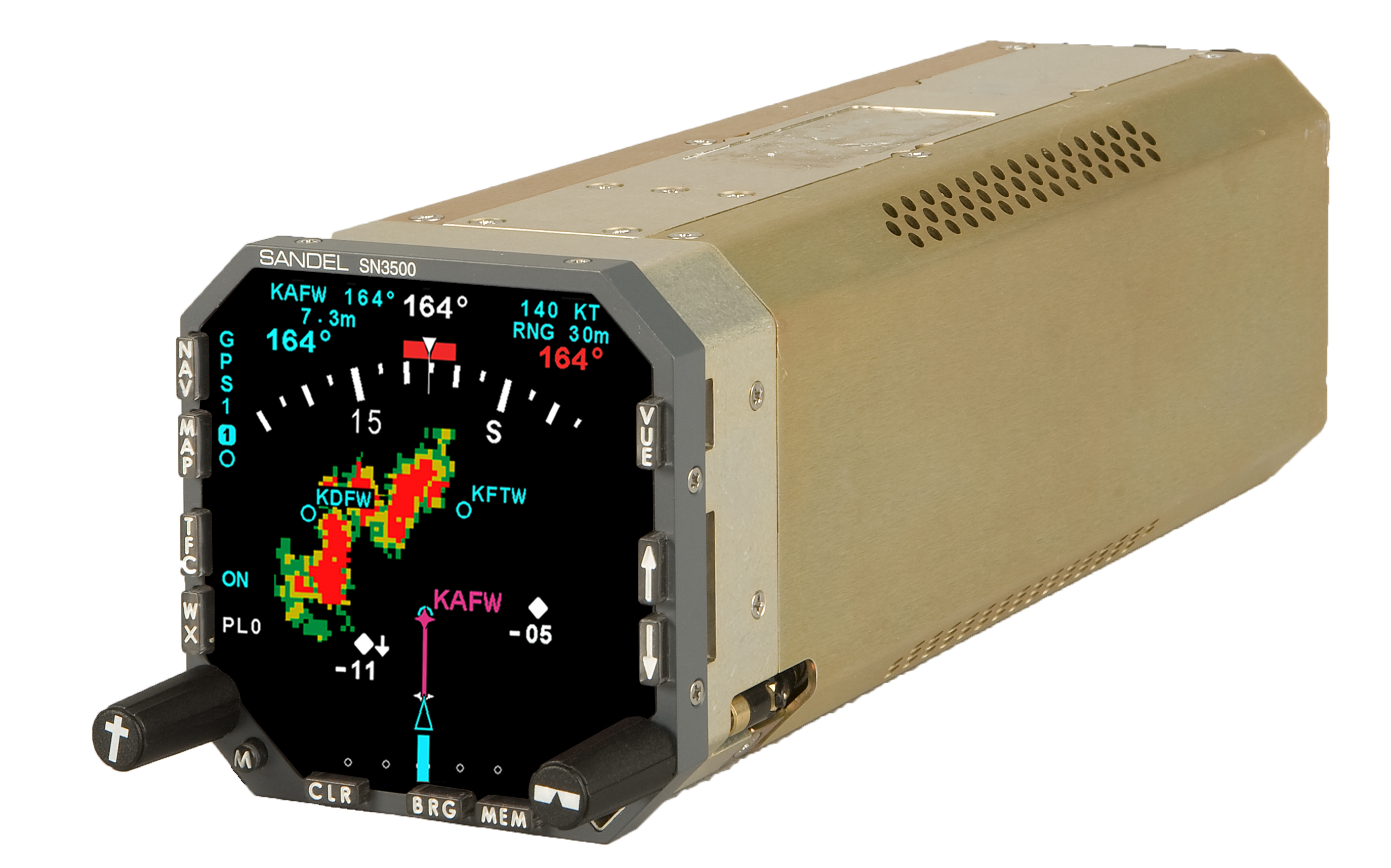
This article describes the installation, including the wiring design, of the Sandel SN3500 (PDF data sheet) Electronic Horizontal Situation Indicator (EHSI)
(above from the Sandel brochure and website)
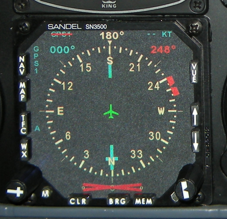
(above from a real installation in another TB20)
in a Socata TB20GT aircraft

The SN3500 was installed to replace the existing Bendix-King (Honeywell) KI-525 HSI - an intricate mechanical instrument designed in the 1970s
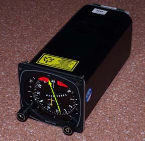
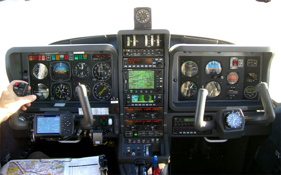
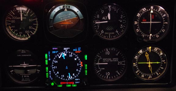
in the TB20 instrument panel below
The original KI-525 HSI is P/N 066-3046-07 which lists at $8200 new or $5000 new-exchange (discount pricing Feb 2011).
The GPS installed in this aircraft is a Honeywell KLN94. This GPS was commonly installed in 1990s-era GA aircraft. Most of this article would be equally applicable to a Garmin GNS430/W or GNS530/W GPS. According to Honeywell (3/2011), production of the KLN94 ceased in January 2011 and there are no planned upgrades.
This article is detailed - to document the installation so that others can install this instrument easily, in a TB20 or another aircraft with similar 1990s-era avionics. The SN3500 makes good economic sense if replacing a KI-525 HSI which needs a repair.
Sandel EHSIs use an unusual display technology: a light source in the back of the instrument, shining through an LCD and rear-projecting the image onto a screen on the front of the instrument. This yields a display area which is nearly the entire front of the instrument. Early Sandels used an incandescent lamp as the light source, which had a short life of 100-200 hours, delivered poor sunlight and wide-angle readability, and got the company a bit of a bad name. The lamp was later replaced with a high brightness LED which does not have the life issue and the display is vastly improved.
Objectives
These are not listed in any particular order.
The SN3500 improves situational awareness by displaying overlaying data. For example you can have a traditional HSI display and a pointer to a VOR, and much more...
The SN3500 digital presentation of the heading makes gross errors much less likely. With a normal HSI it is easy to set a slightly (or not so slightly) incorrect heading when being vectored in a high workload situation.
The SN3500 provides a useful backup of data displayed elsewhere. The SN3500 can duplicate the information from the KN73 DME, the KX155A NAV1 and KX165A NAV2 VOR receivers, the KR87 ADF, marker beacons from the PMA7000 intercom / marker beacon receiver, the WX500 stormscope data currently displayed on the KMD550, and the current GPS track displayed on the KMD550 and the KLN94. It thus provides a backup for the case of a failure of the display in the primary instrument. The SN3500 also provides an additional level of backup for the basic VOR/LOC navigation data: even though the NAV1 CDI display could be generated from the old HSI signals (which come from a KN72) it can generate a CDI presentation from the NAV1 composite signal which comes directly from the NAV1 radio, which is more accurate and reliable because it does not use the KN72.
Course pointer (CP) auto-slew. At each waypoint, the CP flips round to the next track, enabling the entire enroute section of a flight (assuming it is flown in NAV mode) to be flown hands-off. This feature can be user-disabled, and needs to be disabled when the GPS is in the OBS mode.
Automatic steering when using the autopilot. In EHSI installations where the autopilot simply follows the HSI CP, automatic turns are a direct consequence of the CP auto-slew. The aircraft automatically turns onto the next track, at each waypoint. No additional hardware is required.
There have been indications that PRNAV certification may require an auto-slewing EHSI. This topic has been kicking around the FAA and EASA for some years and currently neither requires it. However, PRNAV would require the KLN94 to be ripped out as well. PRNAV is not yet an operational issue in light GA in Europe, and even less so in the USA.
The SN3500 should be more reliable than the mechanical HSI, which is particularly relevant for the ILS indication... If there is a fault with the existing HSI, there is right away a reasonable economic case for the SN3500.
The SN3500 should be more accurate than the mechanical HSI, due to the elimination of backlash, etc.
Reversion to the original KI-525 HSI must be possible. This is partly to avoid the risk of downtime should something go wrong during the installation, and partly to minimise the AOG (aircraft grounded) risk. I will keep the old HSI as a spare; a spare SN3500 would cost $8900 plus shipping and VAT.
Why not the Aspen EFD-1000?
Everybody asks this...
(a) Everybody I know has had problems with that product. Mostly they are connected with the remote sensor unit but some I know about have failed totally, with some pilots having had multiple failures. It looks like Aspen are having significant QA issues. The company is responsive, but that doesn't help with the downtime and the loss of confidence in one's aircraft.
(b) I do a significant number of long flights into parts of Europe which are very nice to visit but where avionics service facilities are practically nonexistent. I would not do those flights unless I had a high confidence in the aircraft. I need every major instrument to be replaceable with a straight swap. This rules out today's popular "glass cockpit" options like the Garmin 500 which require confidential configuration information which is accessible only to authorised Garmin dealers. Admittedly a complex instrument like an SN3500 will always need reconfiguration but that is just a matter of having recorded the existing configuration... If I could get a solid state replacement for the KI-256 vacuum horizon I would do that too, but that is tricky due to the TB20 having just one alternator so the reliability of an all-electric solution is illusory. The solution would come in the form of a small alternator mounted into the vacuum pump drive, and these do just about exist today.
(c) The EFD-1000 makes a bit more sense if one is using it with the EA-100 autopilot adapter, to replace a KI-256 vacuum horizon. But you now have another "box" which is brand new and untested in the market, on top of another one which has been tested and is having significant QA issues...
The SN3500 is not a cheap instrument but field feedback suggests that it is of high quality and is reliable.
Replacing a KI-525 HSI with an EHSI is a fairly common requirement, and another EHSI option is the Honeywell KI-825

but this is less functional, has a smaller display, is overpriced and is poorly supported by Honeywell who over the past decade have essentially abandoned the GA avionics market. Interestingly, the KI-825 is available with a KI-525 conversion harness to ease direct-replacement installations, which is how this project was done.
Why not the SG-102 AHRS?
This is a Sandel solid state gyro product which replaces the KG-102A directional gyro and the KMT-112 fluxgate magnetometer compass. It is an impressive product and its installation facilitates the use of the SN3500's reversionary-horizon mode (a software option which is enabled by the purchase of a $980 key).
However, the SG-102 appears to have a major drawback: it cannot restart when airborne, following a power interruption exceeding approximately 6 seconds. Both the heading stabilisation and the reversionary horizon features are lost. It is thus not certified for use as a primary horizon. It is not the only piece of AHRS-based avionics which has that problem. Garmin (G500/600/1000) and Aspen (EFD-1000) get around it by introducing GPS or airdata into the gyro to tell it when the aircraft is assumed to be "upright". I consider this issue to be unacceptable for such an important piece of equipment. The old KG-102A is not that expensive to buy or overhaul so I kept it.
Update 2014: The SG102 was installed (see notes near the end of this article) and works superbly. In reality it does restart OK during a flight - provided one is flying straight and level when doing it, in smooth air.
Why not throw away the KLN94 and put in a Garmin 430W or a GTN650?
Everybody asks this too... one could replace the KLN94 and the upper (KX155A) radio with one of the above and have a bit of vertical space left over. However, the KLN94 does everything needed for real European IFR flight. It's only issue is that its database does not have any RNAV SIDs/STARs (it does have their individual waypoints, curiously, which can be manually loaded into a flight plan, which is a minor irritation a few times a year). There is a possible longer term issue in that it can never be PRNAV certified and would be a serious operational issue if any PRNAV-only airspace arrived. Installing a Garmin GPS would also open other cans of worms: the KMD550 will not display the OBS mode bearing (this is a known issue) so would need to be replaced, perhaps with an Avidyne EX600, and right away one is looking at a huge avionics job. Of course the EX600 does a lot more but the extra stuff is expensive: a European Jeppview subscription is about £2000/year.
Some notes on avionics upgrade options can be found at the end of this article.
Why not move the old HSI to the RHS?
This is what many EHSI owners have done. It remains a future project. However I would probably re-do the whole RHS panel in that case, such that the main "T"-scan is possible. Replacing the electric horizon with a Castleberry one which emulates the KI-256 would be a super backup option but having the autopilot switchable to use either horizon might be an "interesting" paperwork project because - of the individual-instrument options - only the KI-256 is certified to drive the KFC-225.
Update 2014: a second SN3500 was installed on the RHS. See notes near the end of this article. The original KI525 was sold on US Ebay.
Why not get an avionics installer to do the whole job?
Obviously this type of installation would be traditionally done by an avionics installer (ideally a Sandel dealer) but in this case I decided to do the design and approval documentation myself, pre-wire it to the maximum extent possible, and get an avionics installer to do the final installation and calibration. I did it this way for several reasons:
Avionics Integration: The SN3500 has a lot more functionality than the old HSI but getting the most out of it involves a lot of connections to the existing avionics. Some of these connections give rise to subtle interoperability or functional limitation issues, and I wanted to discover any gotchas before the job was started.
Cost: UK avionics shops quote a high cost for the installation - at least £6000 - and this is on top of the instrument itself of around $9000 (US price; the UK "list" price is higher). Most of this installation cost is a generous budget for labour.
Downtime: Most installers quote 2-4 weeks for doing the work, which is an unacceptable downtime, especially as this is invariably optimistic. With some project management, it can be done in a few days, maximum. Ideally it should be done while the aircraft is having its Annual (with a company which allows avionics work to be done in their hangar) which more or less ruled out all UK avionics installers, but that was exactly what I did.
Bench Soak: To minimise the chance of an early instrument failure, I decided to purchase the instrument and bench-run it (with just power connected) for several weeks.
I had originally intended to get the SN3500 installed wholly by an avionics installer. Over a period of more than a year, I tried to obtain quotations from installers; mainly in the UK. Perhaps 50% were interested in quoting, but a larger issue with those who did quote was nailing down the avionics interoperability. A particular suspect was the OBS mode which has well known incompatibilities between manufacturers. Only one UK installer was willing to discuss it but he now does very few Sandel installs and did not have a clear recollection of the SN3500-KLN94 functionality. The avionics business has moved on to "glass" cockpit products and there is very little EHSI-only work going on. The other installers were happy to do the install but apparently only with no prior discussion; only a mug should go for that. When I started digging around through the installation manuals to educate myself on how it was all going to work, it quickly became obvious that doing the design would not be hard... Then I tried to find an avionics installer familiar with the SN3500 to do the installation and configuration on an hourly rate, but this was unsuccessful too. The installation was done by a freelance avionics installer.
It is an interesting project which should improve the aircraft in a small but significant way, without introducing major risks.
Reversion to the KI-525 HSI
The option to reinstall the KI-525 at first appears complicated but in reality is easily achieved if several things are done:
(a) The SN3500 is wired to the existing KI-525 cable harness connectors to the maximum extent possible, via a short converter cable. This is a good procedure anyway because the converter cable can be entirely pre-made outside the aircraft and this saves about a week's work in an avionics shop - a lot of money. This also enables the SN3500 to be almost entirely tested without mounting it in the panel, which avoids downtime which would result from a wiring error. The only downside of the converter cable is the theoretically reduced reliability due to the extra connectors, but in this case (a nearly new aircraft; always hangared) everything will be as-new and clean, and the connectors are all very high quality.
(b) The installation avoids creating dependencies among existing avionics for information coming out of the SN3500, and which is additional to the capabilities of the KI-525. For example, the NAV1 VOR mode should work OK because the HSI was doing that (the HSI was hard-wired for NAV1 only; no NAV2 capability) already but extending NAV1 functionality to NAV2 fully (e.g. enabling autopilot functionality on NAV2) would prevent a removal of the SN3500. This was all neatly solved by retaining the existing NAV/GPS switch which in turn forced the SN3500 to be installed in Slave mode, which supports only GPS/NAV1, with NAV2 visible only as an RMI. Similarly, the WX-500 stormscope display control remains partly on the KMD550. Some of these issues could be solved with complicated switching but this is not worth doing.
(c) No attempt is made to "optimise" the installation by removing equipment no longer required. The TB20GT contains a KN72 signal converter under the LH seat, which is needed for the KI-525 HSI (unless the NAV1 radio is a KX165 or KX165A which has the KN72 internally). The SN3500 does not need the KN72 (it can be configured to use the composite signal from the NAV1 radio) and the associated lengthy wiring could be stripped out. Why the KN72 was located under the seat, or why didn't Socata use a KX165/165A radio which has this built-in, is anybody's guess. The KN72 used to have a high failure rate, largely due to being full of cheap trimpots, but the post-1999 versions are much better. However, the KN72 has to be left in for autopilot operation with non-GPS lateral NAV sources (VOR/LOC), unless more complicated wiring is put in place. Update 1/2013: the KN72 was removed and the autopilot is driven from the SN3500's lateral outputs (in NAV/LOC mode); see later notes.
(d) Calibration of the system (e.g. instrument nulls) is done in the SN3500 to the maximum extent possible - rather than e.g. in the KLN94 or the KFC225. The KA-51B slaving accessory needs to be retained with the old HSI as the adjustments inside the KA-51B correspond with the KMT-112 fluxgate. The fluxgate itself should not be adjusted (by rotating it in its mountings).
Update 2014: when the 2nd SN3500 was installed on the RHS, the whole harness was re-done more neatly and without the ability to reinstall the old KI525. I judged the SN3500 to have a superb reliability. See notes near the end of this article.
Design Procedure
The Sandel SN3500 Installation Manual (IM) contains virtually all information required to connect the instrument to a wide variety of other avionics from that era (1990s and before). For the TB20GT, 99% of the wiring is straight out of this IM. The vast majority of general avionics installation work is done this way - using the schematics in the back of the IMs. Most people would be suprised at how easy this is - assuming some basic knowledge of avionics functionality and interfaces.
For replacing an existing KI-525 HSI, the SN3500 IM provides a convenient starting point with this page which gives you nearly all the wires required to establish the basic HSI functionality. The job is particularly easy because one is connecting to the old HSI connectors to the maximum extent possible and these already carry the "right" signals.
For the remaining functions (e.g. connecting the DME to the SN3500) one works through the interfacing example schematics in the back of the IM one by one. This simple process yields about 99% of the required wires.
Finally, it is a good idea to individually double-check every wire going to the existing HSI connectors against the existing aircraft wiring diagrams (see links at the bottom of this article) to make sure it makes overall sense functionally.
The resulting wiring diagram is here: 3500.pdf.
The following issues were identified along the way:
The first one was incomplete aircraft schematics. The TB20 GT variant existed between year 2000 (coincidentally the airframe serial numbers then re-started at 2000 also) and the cessation of all piston aircraft production in 2003. In early GT aircraft, the avionics fit was very similar to the late-pre-GT fit (KLN90B GPS, KAP150 autopilot, etc) and rapidly went through various changes during 2001/2002, ending with a very well chosen configuration (shown in the panel pic above) which was offered with a choice of KLN94 or GNSx30 GPSs, and the KFC225 autopilot. The most "desirable" GT variant is the most recent (2002+, corresponding roughly to airframe serials 2100+) one, and - for European pilots facing some bizzare regulatory threats like PRNAV enroute airspace - the GNSx30 option is a lot more future-proof than the KLN94 one. In common with many aircraft manufacturers, Socata license their maintenance manuals to a US company called ATP who publish a monthly CD subscription, for about $1000/year. For a one-off job this is a silly price but various ATP CD manuals are "floating around"; the last one is dated 2006 and is as final as anything Socata have given that TB20GT production stopped around 2003. Unfortunately, it was quickly discovered that the ATP CD manual for the TB20 contained almost no "GT" avionics schematics... Socata evidently retained this information in-house. The ATP CD product is also of poor quality; ATP seems to start with printed documents, scans them at a low resolution, and many schematics are barely legible. It took several months of digging around but eventually ... SUCCESS ... the complete GT schematics were obtained from a very kind (and nameless) 3rd party, current up to the cessation of production in 2003. I did well to get this stuff because given the average GA aircraft age of 25+ years most avionics work is done with hardly any data on the particular aircraft.
No aircraft-specific schematics were available. The schematics mentioned above are in the form of many sheets. Often there are multiple sheets showing subtly different equipment, with no way of knowing which sheet applies to the actual aircraft. Socata drew it up on many pages (example), which are often presented as a group of very similar pages with "option" numbers on the bottom but with no way of determining which options were installed on a particular aircraft. There is no complete wiring diagram for a "TB20GT S/N XXXX" though clearly there should be. The available schematics can be regarded as a general guide only, but in this case the connections are so simple that this is not a problem; one is merely picking up various existing signals around the aircraft. For example, the DME signals can be accessed on the back of the KDI-572 DME display unit. Socata may have a file which contains details of what went into each airframe, but multiple enquiries on this topic were unsuccessful and I am sure the UK dealer (Air Touring Ltd; went bust ~ 2008) did not have this either.
One needs the Installation Manuals (IMs) not just for the SN3500 (which
is freely available) but for all relevant existing avionics, if the installation
is to have a good chance of working. In some subtle cases it is very helpful
to see internal instrument circuits/schematics which are found only in "maintenance"
manuals (MMs). IMs are hard to find and MMs are even harder but fortunately
all those applicable to the TB20GT's 1990's avionics have "escaped"
into the wild and are easily located on the internet. I have a huge collection
of this stuff. "Glass cockpit" manuals remained a well kept secret
but a load of IMs "escaped" in early 2011; of limited use as most
glass-cockpit avionics require closely guarded dealer-only software configs.
I am an electronics engineer with about 35 years' hardware/software design experience
but could have never done this job without the manuals. In general, it is much
easier to find MMs for the Bendix/King / Honeywell equipment than for Garmin
equipment. If you ever buy a new aircraft, try to make it a condition of purchase
that the dealer unofficially throws in all the avionics manuals (on a DVD),
and the last ATP CD ![]() It will save you a lot of money later on.
It will save you a lot of money later on.
Display dimming. On the pre-2011 SN3500 product version, the display brightness can be changed only through pilot-accessible config menus, which is unsatisfactory, especially in the TB20 which has nice centrally controlled (single-knob) instrument illumination. The later SN3500 versions support an external dimming input, similarly to the SN3308 EHSI, but Sandel would not be drawn on which serial number this started at. The SN3500 IM (rev. "K") does mention it in its description of the pin functions, but not in the wiring diagrams. One can implement it with a dedicated potentiometer, or with a connection to a 0-28V dimming bus. The dimming input has a property that any voltage below 0.5V produces a full brightness (for daylight use); this is obviously intended to work with traditional aircraft lighting systems which are fully-CCW during daylight, then a click gives you max brightness, and fully-CW gives you min brightness. It also ensures that if the wire breaks you get full brightness. According to Sandel, all SN3500s with the LED backlight have the same hardware and support this feature with firmware v4.03 or higher, and the firmware is easy to upgrade through the front panel USB connection.
The KA-51B slaving accessory, which is used during pre-flight checks to exercise the slaved instruments

and which also contains correction adjustments for the KMT-112 fluxgate magnetometer, is not used with the SN3500 and is removed. The SN3500 has this correction implemented internally, in the config menus. If the original HSI is re-installed, the KA-51B will have to be re-connected so it is best to not cut off its harness connectors. The disconnected KA-51B can be left mounted in the panel but one loses the capability to exercise the rotating compass on other slaved instruments (e.g. the KI-229 RMI) during the pre-flight check.
GPS (flight plan) data needs to be wired to the SN3500. If this is not done, the SN3500 will work but will be stuck with a "NAV1" annunciation even if the external NAV/GPS switch is in the GPS position; this is misleading and uncertifiable. And if one brings in the state of the external NAV/GPS switch, when that switch is in the GPS position one will get a "no GPS data" error message on the SN3500, so this is not a solution either. Unfortunately, the wire (from the KLN94 pin 2) carrying the GPS data runs only within the centre avionics stack and is very difficult to access.
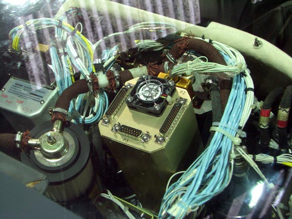
Centre stack pass-through: Any connections made to the inside of the centre stack should pass through the multipole connectors through which all centre stack signals are routed on the TB20GT. For an installer who knows what he's doing, these connectors enable the centre stack to be completely extracted in under an hour - a huge improvement over the pre-GT TB20. It appears easy to install either additional pin inserts in the existing connectors, or install additional ones. There are pre-cut holes in the metal for e.g. a DB15 connector as seen in the middle of this pic. Unfortunately, access to these connectors from inside the centre stack while in the aircraft is extremely difficult and it is a lot easier to run wiring out through a large (approx 3" dia) hole in the back of the stack and fit an inline connector there.
The WX500 stormscope data can be viewed concurrently on both the SN3500 and the KMD550 MFD, but the stormscope functionality is controlled to some (undocumented) extent by sending RS232 messages to it and - short of installing a switch - these can come from only one device, and a decision needs to be made on which one. I decided to leave the control with the KMD550 MFD (a) because these features are rarely used; (b) to preserve the KI-525 reinstall option; (c) because the KMD550 remains the primary means of viewing stormscope data. The SN3500 display can easily get cluttered. Post-installation, it turned out that each display device can set its own display scaling. Also, on the SN3500 the stormscope scale is identical to the general map scale.
Fly-By waypoint turn performance may not be adequate. In most automatic flight the waypoints are fly-by waypoints, and ideally the next track is intercepted exactly:
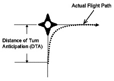
An EHSI delivers automatic autopilot steering implicitly, via its auto-slewing course pointer (CP) which the autopilot simply follows. It is obviously within the capability of an EHSI to optimise the turn for the precise fly-by case illustrated above (it knows the flight plan, track, heading, position, ground speed, etc) by rotating the CP at a specific time and rate, but none of them appear to do anything like that. The CP behaviour could not be established in advance - except that it was relatively "dumb" i.e. the CP slews around and the turn commences some fixed time or distance before the waypoint - because that is where the KLN94 emits the new leg's data. The autopilot then decides the turn rate (or roll angle, in roll-driven autopilots like the KFC225) according to the value of the lateral deviation voltage, with a self-imposed upper limit of around Rate 1. Large turns (above about 30 degrees) hit the autopilot-limited roll angle. This will obviously work well for normal enroute flight where track change angles are small (usually well under 20 degrees) and the turn is completed in a few seconds but it may not be great for flying GPS/RNAV approaches where there is a 90-degree turn onto the final approach track, and the lack of turn anticipation could produce an excessive overshoot. Flight tests showed that this worked to an acceptable standard - see notes near the end of this article.
The traditional solution is to install some form of predictive roll steering (also called GPSS) which involves either a direct GPS-autopilot connection (ARINC429 digital, or analog) or a 3rd party "roll steering converter" (which uses the GPS data to compute the turn parameters and fakes a "heading bug"; the autopilot is then put into the HDG mode). A full optimal-turn computation requires knowing the wind aloft; not just the ground speed on the initial track. With the KLN94-KFC225 combination, the only available roll steering option is the KLN94-KFC225 analog roll steer feature which runs a few wires directly from the KLN94 to the KFC225. I did not install roll steering as it involves difficult access into the centre avionics stack, and requires a later KLN94, P/N 069-01034-0102, which came out in 2003. The KLN94 fitted to TB20GT aircraft will normally be the older 069-01034-0101 which does not have the roll steering output (there is an -0101 to -0102 software upgrade; Service Bulletin KLN91-M1). This roll steering feature also cannot be switched on/off during the flight. Post-installation, the roll steering connection turned out to be operationally unnecessary.
Allegedly, the KLN94-KFC225 roll steering connection requires a relay switching the Valid wire, to invalidate the roll steering signals when the NAV/GPS switch is in the NAV mode. This would be suprising since both the KLN94 and the KFC225 should both be separately aware of the status of that switch. As far as I was able to check with Honeywell, the relay is not required, even though the KLN94 uses its GPS DISPLAYED input only to disregard the OBS data from the HSI when the switch is in GPS mode, and does not use it to enable the roll steering output. I think this would need to be checked out - most likely by seeing if the installation works properly - if roll steering was being contemplated.OBS functionality must be preserved; the OBS mode is used to fly non-precision conventional (VOR/NDB) approaches using the much more accurate GPS guidance. If CP auto-slew is enabled (the default case on the SN3500, if valid GPS flight plan data is being received) the SN3500 CP flips around by itself and cannot be rotated manually (an error message pops up if you try). However, when the GPS is switched to the OBS mode, you need to be able to rotate the CP manually (assuming the NAV/GPS switch is in GPS mode; in NAV mode the GPS does not monitor the HSI OBS setting). Pilots I spoke to just disable the auto-slew using the SN3500 buttons when selecting OBS mode on the GPS. It would be nice if this happened automatically... the SN3500 has two potential ways to detect that the GPS is in the OBS mode: a discrete input (P1/pin15), and the RS232 flight plan data from the GPS. The KLN94 has no discrete output pin but it does output a flag in the RS232 data so that would be the only automatic option. Despite extensive enquiries I was unable to establish in advance whether the SN3500 would pick up that flag from the KLN94 data, but the worst-case scenario was that the auto-slew would have to be disabled manually. Post-installation, it was found that the OBS mode worked perfectly, using the RS232 data.
Another potential interoperability issue related to the OBS feature is that when a GPS is switched to the OBS mode, its output data stream confuses the destination device. It is known that a lot of equipment (MFDs etc) does not display GPS OBS modes correctly. For example, a KMD550 MFD does not display the correct bearing from a Garmin GNSx30. Despite the importance, I was unable to establish this in advance for the KLN94-SN3500 case. The worst case scenario here was a serious lack of functionality in a major instrument but I decided to take a chance on it and on the loss of money disposing of the SN3500 on Ebay... Post-installation, it was found that this worked fine.
Many pilots are unaware of the OBS mode of their GPS but it is extremely useful. It makes it possible to fly a VOR, NDB or LOC/ILS approach, using GPS, accurately, without a published overlay in the GPS database. One can also fly holding patterns with it. However, an additional trick is available: flying a LOC or ILS approach using the navaid for primary guidance but monitoring it (laterally) using GPS in the OBS mode. In most installations, when the NAV/GPS switch is set to NAV, the HSI CP setting is not visible to the GPS so the runway inbound bearing is manually set (duplicated) on the GPS. Then, set a DCT to the airport, and the KMD550 MFD displays the extended runway centreline. It is not a perfect scheme, because (at multi runway airports, especially) the DCT waypoint might not be exactly where the localiser is terminating, but it is useful for monitoring the approach, and having to set the bearing in two places avoids gross errors in instrument settings. This installation preserves this functionality.
The SN3500 supports NAV2 also (and GPS2, ADF2, DME2 if you have these). This is a nontrivial subject which the IM fails to explain properly, but in essence the SN3500 works in one of two modes: Master (nav source selecton is done on the SN3500; successively pressing the NAV button selects the various NAV sources) or Slave (nav source selection is done externally with a "NAV/GPS" switch, the SN3500 senses the setting of the switch, and only NAV1/GPS1 can be displayed in a CDI presentation). Any installation which has GPS2 or NAV2 has to use the Master mode and involves having the SN3500 driving a collection of relays switching potentially many signals. However, a subtle feature in the SN3500 software is that NAV2 can still be connected (as a composite signal only) to a Slave mode SN3500 and it is viewable as an RMI-style needle only (no CDI). This is a great feature which backs up the existing NAV2 indicator(s). The extra ADF and DME inputs are not affected by the Master/Slave status because they are purely display-only features. The DME display uses logical (albeit non-trivial) rules; if you have the KN63 DME (switchable NAV1/NAV2/HOLD) then in GPS mode it is suppressed except when a NAV1/NAV2 bearing pointer is displayed in which case it appears next to the bearing pointer data.
The RMI capability of the SN3500 (both NAV1 and NAV2 VOR inputs can be displayed as bearing needles) makes the existing KI-229 RMI redundant, but I decided to leave it installed because there is nothing useful to put in the hole.
The autopilot may not detect a failure of the SN3500. The SN3500 is
powered via a separate 5A circuit breaker (CB). The existing 2A "HSI"
CB, which actually powers the KG-102 gyro, which in turn powers the KI-525 HSI
and some other related items, is retained. The AP gets a "heading valid"
signal from the KG-102, and this signal also goes to the SN3500. But if - for
example - the SN3500 CB is pulled, the AP still sees a "heading valid"
signal from the gyro, but the heading deviation value, which comes from the
SN3500, is now zero, which to the AP is indistinguishable to a perfectly centred
heading bug. The AP, if in HDG mode, will gradually drift off the heading without
any warning. The rather contrived CB-pulling scenario could be addressed with
a relay which breaks the "heading valid" signal to the AP but it is
obviously imposible to detect a subtle internal failure of the SN3500 itself.
If the AP is in NAV mode (tracking LOC or GPS) a SN3500 failure may or may not
be more obvious given that it is driven laterally from the KN72 and vertically
from the NAV1 receiver - not via the SN3500. In the end, detecting instrument
failures is what the pilot is for ![]()
A 220 ohm resistor (see Note 6 here) needs to be connected to emulate the load of a resolver coil which was present in the now-removed HSI. Here is some information on synchro / resolver stuff. The coil in question is connected to the HSI "a" and "X" terminals here. Those terminals are driven (in NAV mode) from the KN72 terminals 13 and 1 (1 is ground). A SN3500 IM page tells you exactly where the resistor goes; what is less obvious is that in this type of "NAV+GPS" installation (which is hardly unusual) the 220 ohm resistor should be present only in the NAV mode, not in the GPS mode, so it has to go before the relay which switches the NAV/GPS signals to the SN3500. The SN3500's high impedance inputs do not load up the KN72's outputs in the way the old HSI did - hence this load resistor. More modern avionics appear to be designed to be relatively load-insensitive but the KN72 is definitely not in that category and it is obvious from its schematic that the correct load is required on pin 13.
For a similar reason to above, other dummy load resistors may be required elsewhere, because one is replacing an instrument which contains specific loads (1k on most analog inputs; 200 ohms on the coil operating the TO/FROM flags) with an instrument whose inputs are all high impedance. The SN3500 IM hints at this issue in an obscure footnote. An examination of the schematics of the NAV receivers which drive the HSI interface (KN72 for lateral nav, KX155A for the GS, a KLN94 schematic was not available) suggest that dummy loads should not be required because all the outputs are driven from op-amps whose feedback is taken from the final output, but all the installation data I found talks about 1k and 200 ohm loads, so it is quite plausible that the designers of this equipment never checked for e.g. marginal stability when driving a high impedance load. This stuff is too safety-critical for a "suck it and see" approach so, to be sure, the correct 1k and 200R load resistors were installed within the conversion harness, and are shown in the PDF schematic. This was a slightly tricky job, especially for the 1k GS resistor which needs to be squeezed inside the already packed 44-way connector shell. The other resistors fitted more easily inside the large metal shells. Even though the SN3500 can be configured to internally decode the NAV1 composite signal and thus would not care about the lateral deviation voltages being correct or even present (and the KN72 could be removed altogether), the KFC225 autopilot remains driven laterally from the KN72 outputs. Update 1/2013: the KN72 was removed and the KFC225 is now driven from the SN3500's P2 output, in VOR/LOC mode only; in GPS mode it remains driven from the KLN94.
The mounting kit requirement, for mounting the SN3500 in a KI-525 hole, proved difficult to establish in advance. The instrument is held using a mechanism where two of the four screws hold the mechanism to the panel, and the other two screws tighten up a clamp around the instrument. The SN3500 IM shows a "standard" mounting and a "flush" mounting. These pics 1 2 show a "standard" TB20 installation which looks a little rough due to the damaged panel. This one shows an apparently identical installation but which is much neater due to the use of a non-functional front bezel whose origin has not been determined (which could obviously be fabricated from a 3mm sheet). In general, fully flush mounted avionics are difficult to use in turbulence because there is no edge against which to rest one's finger while operating the buttons. In the end I bought all (2) available mounting kits to see what comes in the bags.
In keeping with avionics industry traditions, Sandel dealers are not allowed to sell the product bare. They are allowed to sell it only with an installation. Some US dealers get around this by selling it with a generic cable harness and advertising it "for Experimental aircraft only"; it is obvious the instrument is the same one but it is not always clear whether you get the 8130-3 form in this case. Fortunately, some US dealers are happy to just sell the standard instrument, direct, although most of them sell it at the $11000 end user list price. Only a few sell it at the fairly commonly advertised $9000 discounted price and sell it direct. European dealers sell it direct too but they mark it up about 30% over the end user list price. Obviously I am not going to say which dealer I got the unit from. I checked with the dealer that they would honour the warranty if I return the unit to them at my expense, which is reasonable. No support (beyond confirming the part numbers) was provided by the dealer.
The "dealer-only" policy also restricts who will install the instrument. Most large avionics installers won't touch customer-supplied avionics - even if it is expressly agreed that the installer will (obviously) not have any liability on the instrument. One is restricted to freelance avionics installers, but fortunately they are not scarce, and neither are FAA A&P/IA engineers who are needed to sign off the finished installation.
Certification Issues
The aircraft is US registered and the installation thus needs to comply with FAA requirements.
The first question is whether this can be installed as a Minor Alteration (done with a logbook entry) or a Major Alteration (done with a Form 337). Both routes require the parts being installed to be supported by Approved Data.
In the maintenance business (in the field) the decision whether something is a Minor or a Major alteration is done by an FAA IA, or an FAA Part 145 Repair Station.
The main reference guide for the Minor v. Major decisionmaking is here (local copy).
The FAA Major Alteration definition list is FAR 43 Appendix A (local copy) and much depends on the meaning of the words "changes in the basic design of radio communication and navigation equipment ....." [my italics]. The flow chart on page 18 (of the PDF) of the Major v. Minor decisionmaking guide shows the direct route to a Minor Alteration decision if e.g. one can justify that the SN3500 installation is not a "basic design change".
However, there are additional guidance documents which are more specific to EHSIs. This one (local copy) talks about the Sandel SN3500 using the words "field approval" which suggests that the writer was thinking of a Major Alteration. The aforementioned document is also referenced here (local copy) and this again suggests a Major Alteration. Here is another take on it, though it is more relevant to non-TSO avionics.
According to Sandel, the SN3500 needs an Aircraft Flight Manual Supplement (AFMS) and while this does not in itself mean it is a Major Alteration, it is another nail in the coffin of the Minor route because while one can edit the sample AFMS provided by Sandel, it needs to be FAA approved and one can't get it FAA approved unless it is submitted to an ACO (Aircraft Certification Office). This is usually done by forwarding a hard copy of the document with a place for the FAA approval signature and date on the cover and on each page, a place for a signature/date or initials and date.
B. Alterations Requiring a Flight Manual Supplement. Alterations requiring a flight manual supplement or operations limitations changes must be coordinated with the ACO, unless the Flight Standards (AFS) inspector has been specifically authorized by AFS to sign the document(s).
However it is far from clear that an AFMS is mandatory. AC43-210 says
a. An aircraft alteration that changes the operating limitations or procedures necessary for safe operation is a major alteration and must include an AFMS if the aircraft has an Aircraft Flight Manual (AFM).
Clearly, an EHSI does not change the procedures necessary for safe operation of the aircraft...
A lot of equipment of this type (replacing an existing HSI with an EHSI) is routinely installed (in the USA) as a Minor Alteration. No FAA-approved AFMS is delivered; the SN3500 Pilot's Guide is used instead. Practically, the AFMS is a very brief piece of certification formality anyway and contains little useful information; the Pilot's Guide is the real "user manual". And, according to one of UK's biggest installers, EASA installations of the SN3500 do not need an AFMS, which is suprising since EASA is normally heavily anally retentive.
A supporting factor for the Minor route is that - in this installation - the SN3500 will not control anything in the aircraft beyond what the old HSI did. All the additional SN3500 functionality is limited to inputs to the SN3500. If we brought in NAV2 in such a manner that one could drive the autopilot from NAV2, that might be different...
A good reason for going for the "gold plated" Major Alteration route is that it enables the installation to be published to help other owners of the same aircraft, without a concern for somebody taking a different interpretation at some future date and causing trouble...
All Major modifications require "approved data" and involve the completion (by an FAA IA or an FAA Part 145 Repair Station) of a Form 337.
What is Approved Data? There is a list in AC43-210 (local copy) on page 11 of the PDF.
Of particular note is this one
(6) Appliance manufacturers’ manuals or instructions, unless specifically not approved by the Administrator, are approved for major repairs.
which enables the use of an Installation Manual (IM) as approved data. In this case this is important since the SN3500 IM contains generic schematics for every single connection to the existing aircraft avionics!
Who decides whether the approved data is good enough? An FAA IA, or an FAA Part 145 Repair Station. However, this decision is not legally bulletproof. It is possible, during an inspection or following e.g. an accident, that the FAA itself could disagree with the aforementioned's opinion. This happens very rarely, but if one wants to cover one's back totally, one needs to apply to a Field Standard District Office (FSDO). The FSDO performs "quality control" on the approved data, completes box 3 on the 337 form, and returns it to the installer. Once the installation has been done, the IA or the Repair Station inspects the installation for conformity to the approved data (listed on the back page of the 337) and uses box 7 on the 337 to return the aircraft to service. The 337 is then sent to the FAA in Oklahoma for filing. This is a popular "field approval" route for US based installers.
Unsuprisingly, many installers use the FSDO field approval route (which is a free facility provided by the FAA) to sidestep having to understand the approved data requirements, and they file a 337 for "everything". The FAA has on occassions expressed its irritation over installers filing 337s for all kinds of trivia.
In this case, with the aircraft located in Europe, the FSDO responsible is the New York International Field Unit (NY IFU). Unfortunately, the NY IFU stopped doing avionics field approvals some time ago, and confirmed this in Dec 2010. This policy contravenes an FSDO's duty but there is nothing one can do about it from this end. This apparently leaves only one way forward: get the IA (or an FAA Part 145 Repair Station) to send the 337 direct to Oklahoma (for filing). This in turn means that the approved data submitted with the 337 must be beyond reproach.
There are also very few FAA Repair Stations in Europe, with the appropriate scope of approval for this type of work. Currently, the FAA is not allowing any new Repair Stations to start up outside the USA.
This leaves two approaches for generating approved data which "should" be OK:
a) Find enough in the above list a) to s) and send the 337 direct to Oklahoma, for filing.
b) Pay an FAA Designated Engineering Representative (DER) to generate the approved data. He generates an 8110-3 form which is sent off with the 337 to Oklahoma for filing.
In Europe, because the NY IFU is not processing field approvals, method (a) is popular with FAA Repair Stations, whose opinion on approved data is rarely questioned by the FAA. Method (b) is popular with other classes of installers, largely because the use of a DER gives the installer a hook on which to hang a "due diligence" coat. The opinion of a DER on approved data is rarely questioned by the FAA. Neither of these methods is as legally watertight (in protecting the installer and the aircraft owner) as getting a straight field approval via an FSDO.
Unfortunately, a DER is of no help if an individually FAA approved AFMS is mandatory. That still needs to be done by the FAA... somewhere. I don't know how the firms that use a DER work around this one. One obvious way is to not supply an AFMS, or to supply one which is not FAA approved. Very few owners would notice because the formal AFMS usually contains very little useful information; one refers to the Pilot's Guide for operation. Another way is to use a "private" contact in the USA to submit the application to an ACO. This is not an issue with an AML STC product such as the GNS430W which comes with an AFMS which does not need to be individually FAA approved. However, there is a potential gotcha with AML STC products in that the letter of authorisation to use the STC may be expressly limited to Garmin dealers, precluding an independent installation! To protect the STC holder's "intellectual property", the FAA does nowadays require this letter of authorisation if an STC is used as Approved Data.
Locating a communicative DER proved to be extremely difficult. This business works hard to discourage contact with end users so to get any response communications need to be done using an "aviation business" type of contact name and email address. Through a circuitious route I discovered several very expensive DERs, plus one DER who works at .... Sandel. Ultimately I never contacted any of them.
Another DER facility is an in-house one at South East Aerospace - a well known US company which exports avionics worldwide. I have been buying bits from them for years and their customer service is generally very good (albeit with absolute adherence to the warranty small print regardless of the fault history of the item). They sell a lot of avionics direct but won't sell the SN3500 direct, bare. They did offer to sell it with various items including an 8110-3 design package produced by their DER. Their quote for the 8110-3 was an eye-watering $10,000 (plus the cost of the SN3500) and their terms contained some clauses which were practically meaningless to comply with e.g. the supply of all wiring diagrams for the aircraft; obtaining an FAA approved AFMS; etc. For $10k one could get the unit installed in the UK... I am not sure who pays these prices - especially in the USA. A totally clue-less installer, perhaps, with a totally clue-less customer.
However, via another circuitious route I discovered a way to do a conventional FSDO field approval: send the 337 to any FSDO which agrees to process the application. With this co-operating FSDO, I followed the standard 337 route. It took a few small edits to get everything to an acceptable state and then it took only a few weeks for the FAA-approved documents (an approved 337, and an FAA-stamped AFMS) to arrive, returned to me by Fedex. A totally wonderful service. The final submitted documents can be found at the and of this article. The 337 application made use of various Approved Data including the wiring diagrams, and the contents of a Cessna 421 STC which Sandel had.
Regrettably, I am unable to report that this FSDO will be a long term solution available to European pilots, due to some opaque politics. There is a clear business opportunity for a US contact willing to submit 337s etc on behalf of a European-based aircraft owner, and then any FSDO can be used. If I find an FSDO which is clearly and openly willing to support customers outside the USA, I will add their details here.
Looking at the returned papers, the AFMS was in fact subcontracted to and approved by a different FAA office; an ACO. I have another project coming up which is an AFMS-only job (no equipment installation involved) and will give this ACO a try directly.
Update 7/2014: The FAA has released a guidance note (local copy) and an EHSI is on page 15.
Required Parts
The following items were purchased from a Sandel dealer:
(1) SN3500 EHSI Black P/N 90165 $8889.00
(2) KI525 shim kit P/N 90124 $214.00
(3) Installation kit P/N 90143-IK $429.00
The European database was specified at time of ordering.
Interestingly, the 8130-3 which came with the unit was signed by a DAR and carries the words "for export to the UK" on it. This is not required for an N-reg aircraft but could be relevant to a G-reg depending on what use it is put to (commercial, etc). I did not request this so somebody somewhere was smart.
Apart from wiring, the other items required for the installation were:
(1) The two 41-way Positronic GMCT connectors which plug into the KI-525 hardness connectors
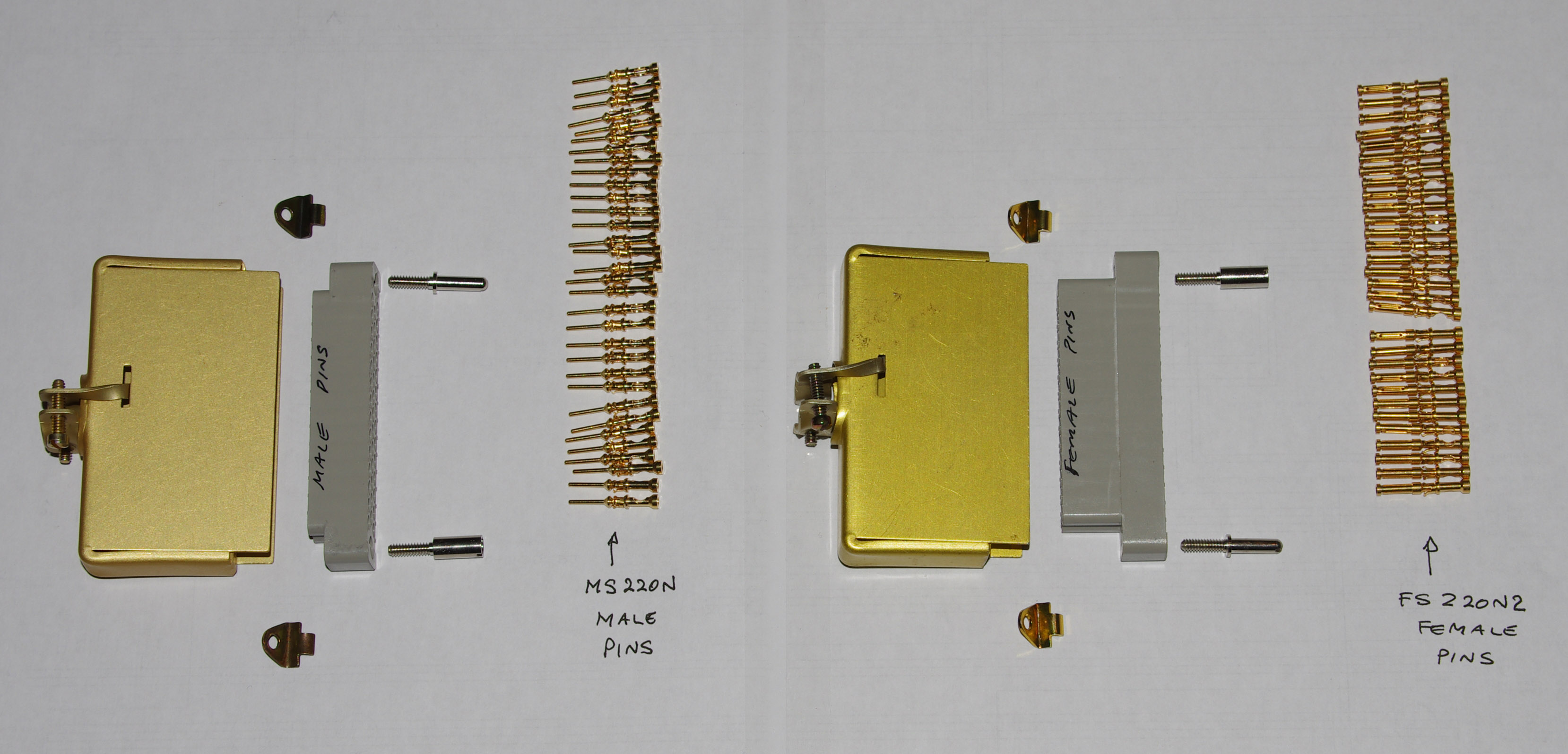
The above connectors need to look like exactly those on the back of the old KI-525, right down to the retaining clips
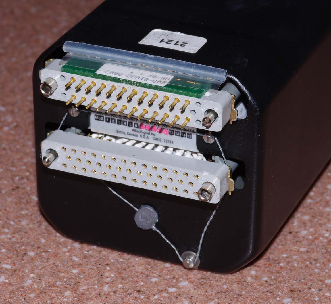
Sorting the correct part numbers for the cable shells, pins/sockets (1mm diameter pins) and retainers was a non-trivial job which was done with some great help from Positronic UK. The delivery time on these parts was some weeks. Within the avionics business, these connectors would likely have been extracted from a scrapped KI-525 HSI but all those I came across were very old units with corroded connectors; also the old connectors used short male pins which did not appear to mate fully with the much newer TB20GT harness connectors.
The order codes (checked with Positronic 2/2011) are:
GMCT41F0N00JV (female connector with 'N' guides, 'J' hood and 'V' clips)
GMCT41M0N00JV (male connector with 'N' guides, 'J' hood and 'V' clips)
Note: Winchester Electronics may make some or all of these connectors too.
I would recommend getting (or borrowing) the proper pin extraction tools for the above connectors. Otherwise, if a pin is inserted into the wrong hole, there is no way to get it out. According to Positronic, the tool for the 41-way KI-525 connectors shown above is P/N 9081-0-0-0 shown here (local copy) and costs about £40.
(2) The 32-way mil-spec circular connector shown in the schematic. This is not necessary but it enables the SN3500 and the entire conversion harness to be removed from the aircraft, leaving behind just the 32-way connector which can be tucked away into the existing aircraft harness. Of course, this connector could be any other suitable type; a DB37, etc. The circular one was chosen for its robustness and small size. The eventual installation used 30 pins, and at least 8 of those were ultimately unused (see notes on the use of the NAV1 composite signal). However, if the autopilot was driven from the P2 outputs of the SN3500 (rather than from the KN72) more pins may be needed.
(3) Two small GH5/GH9 Positronic connectors which plug into the KA-51B harness connectors. The ones I used were cut off from a scrap KA-51B; most avionics shops will have these kicking around their junk box.
(4) SN3500 mounting hardware:
The SN3500 documentation is unclear as to the exact part numbers for the various mounting accessories (they should have included illustrations of the various items) and there was at least one typo in the IM. In the end I decided to just buy both the pricey 90124 and 90143 kits mentioned above, and see what falls out of the bags...
The mounting method can be seen in the following pics:
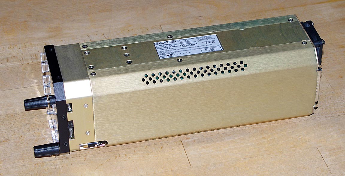
Bare SN3500 instrument:
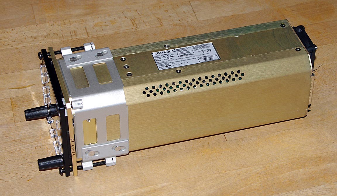
Here is the SN3500 with all hardware required to replace a KI-525. Starting at the LH end, you can see the two components of the 90124 KI-525 kit: a black bezel, then a gap of 2-3mm where the instrument panel ends up, and a plated shim marked "61045". The large clamp around the SN3500 is the 61062 3ATI Mounting Clamp:
The remainder of the 90145 installation kit includes another shim marked "61044A" which is probably pricey but is wasted
![]()
It can apparently be used to fully flush mount the SN3500 (I would avoid full flush mounting because it makes it hard to locate the buttons with one's fingers in turbulence) although that will produce a tacky job unless the instrument panel is re-manufactured with a tightly fitting hole.
It appears that to save wasting the 61044A shim one could forget the Installation Kit and buy the following items:
SN3500 EHSI Black P/N 90165
KI525 shim kit P/N 90124
3ATI Mounting Clamp P/N 61062
Might save $200? It's probably not worthwhile; see notes below on the DB connectors, and you won't get the Pilot's Guide in a nice little ring binder. Those who want to play with metalwork can look at some of these very cheap adapters (local copy), notably the KI525 to 3ATI one ... they might fit. The Sandel metalwork is of very high quality however.
(5) Three SN3500 DB connectors (1 x 15way, 2 x 44way). Sandel include these in the Installation Kit; these are of the standard "avionics" loose-pin style with retainer clips
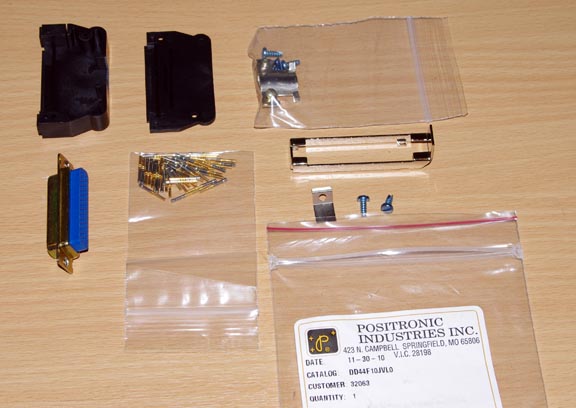
The package labels shows these to be off the shelf (well, with a possibly long lead time) Positronic items: 2 x DD44F10JVLO and 1 x SD15F10JVLO.
While the connectors are standard DB15 and DB44 patterns available everywhere from 50p (for the rubbish ones) to £10 (for mil-spec machined-pin ones), and a credit goes to Sandel for having avoided the eye-wateringly pricey single-sourced Positronic connectors commonly used in avionics, one needs to get the correct shells with the correct retaining clips. The Positronic connectors which were included use shells and retainers - here (local copy) and the retainers can be seen on page 12 of the PDF (VL type) - with subtly different dimensions to the commonly available types - (URL local copy) and the latter types do not retain a DB connector against the SN3500's clips in an adequately engaged manner. Looking at the data sheet, it is likely that the supplied hoods are in conductive plastic, which is good.
I tried to improve on the quality of the supplied DB cable connectors, and also tried to get solder-bucket types instead of the crimp types supplied, but did not find any machined-pin 44-way ones. I easily sourced a machined-pin 15-way mil-spec one and used that in the cable harness. I much prefer soldering (and heatshrinking sleeves over the pins) but if your soldering skills are less than great then crimping will be a lot safer (albeit with a need for some very expensive tools)!
Looking at the DB connectors on the back of the SN3500, I was suprised to find
that Sandel have used formed-pin, rather than machined-pin, connectors on a
$8900 instrument. This saves a few bucks but results in a relatively fragile
connector which needs to be treated with care: a bent pin is likely to just
disintegrate. The harness connectors must be kept very straight during insertion
and extraction. I also found was that the retaining clips on the back of the
SN3500 were not installed straight; the factory
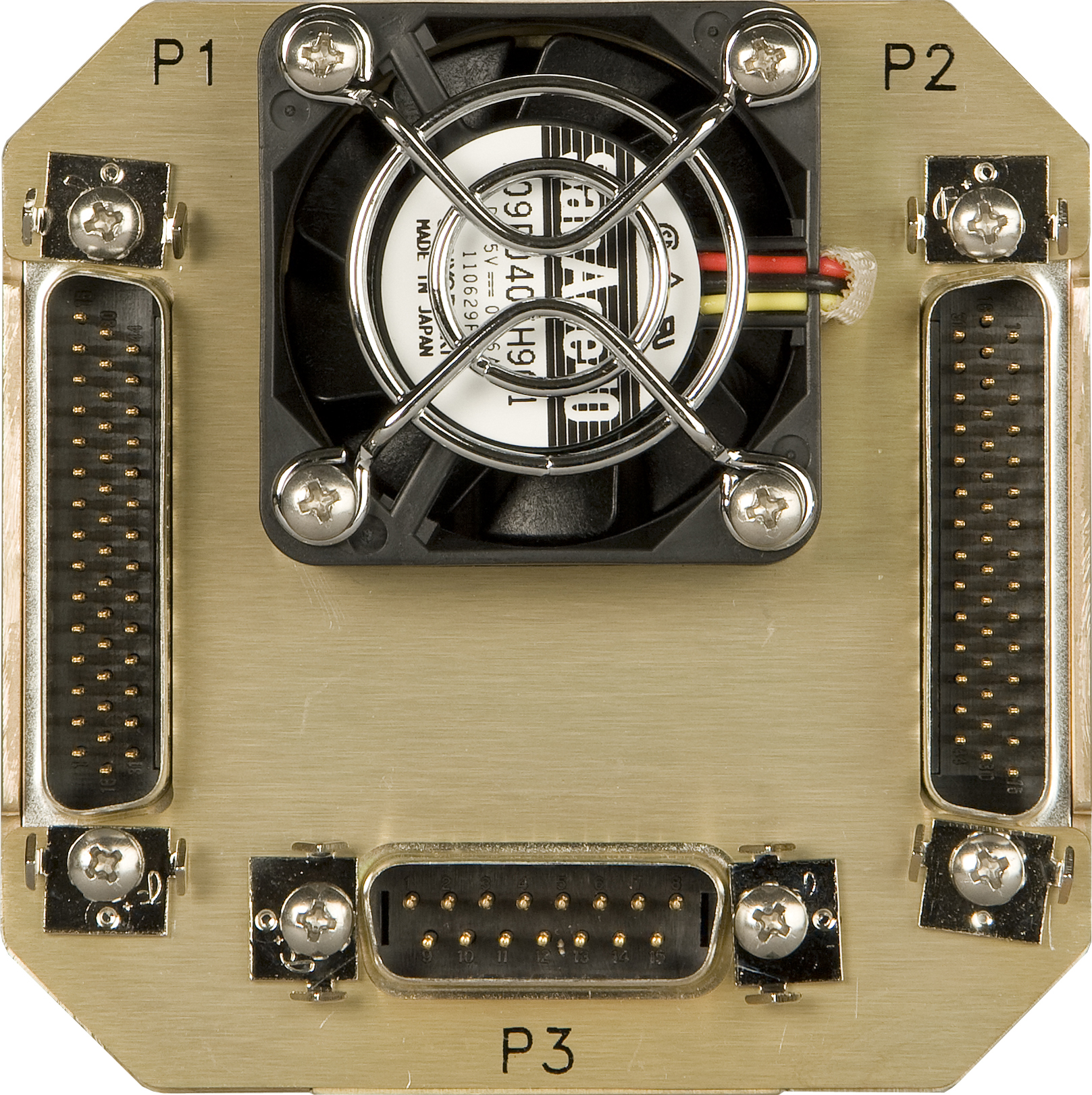
photo shows this rather too well ![]() Otherwise, the build quality of the SN3500 is superb. Unlike a lot of $5000-$10000
avionics, with flimsy PCB-mounted connectors sticking out, this is a solid piece
of equipment. The fan on the back of it is a Sanyo one and they are the highest
quality fans available.
Otherwise, the build quality of the SN3500 is superb. Unlike a lot of $5000-$10000
avionics, with flimsy PCB-mounted connectors sticking out, this is a solid piece
of equipment. The fan on the back of it is a Sanyo one and they are the highest
quality fans available.
(6) A 5A circuit breaker is required. Sandel do not specify the breaker characteristics. To match the existing Socata ones, the Socata 5A pull-off breaker P/N is N7173010053 and purchased from Socata it came to about £50. It is made by ETA (local copy data sheet), P/N 4120-G111-K1M1-A1S0ZN-05A as shown below. Very similar circuit breakers are made by Klixon for about $25. It was mounted (labelled "EHSI") in a spare location next to the 2A KG-102 CB which is marked "HSI".
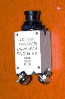
The actual current drawn by the SN3500 was measured at 0.47A-1.24A at 28V, with the variation being wholly due to the display backlight setting. At 24V the maximum current increases to 1.38A, indicating the use of a standard switch-mode power supply.
Conversion Harness
As described above, the SN3500 was installed using a conversion harness which connects it to the two existing KI-525 connectors and to other signals which come from other avionics
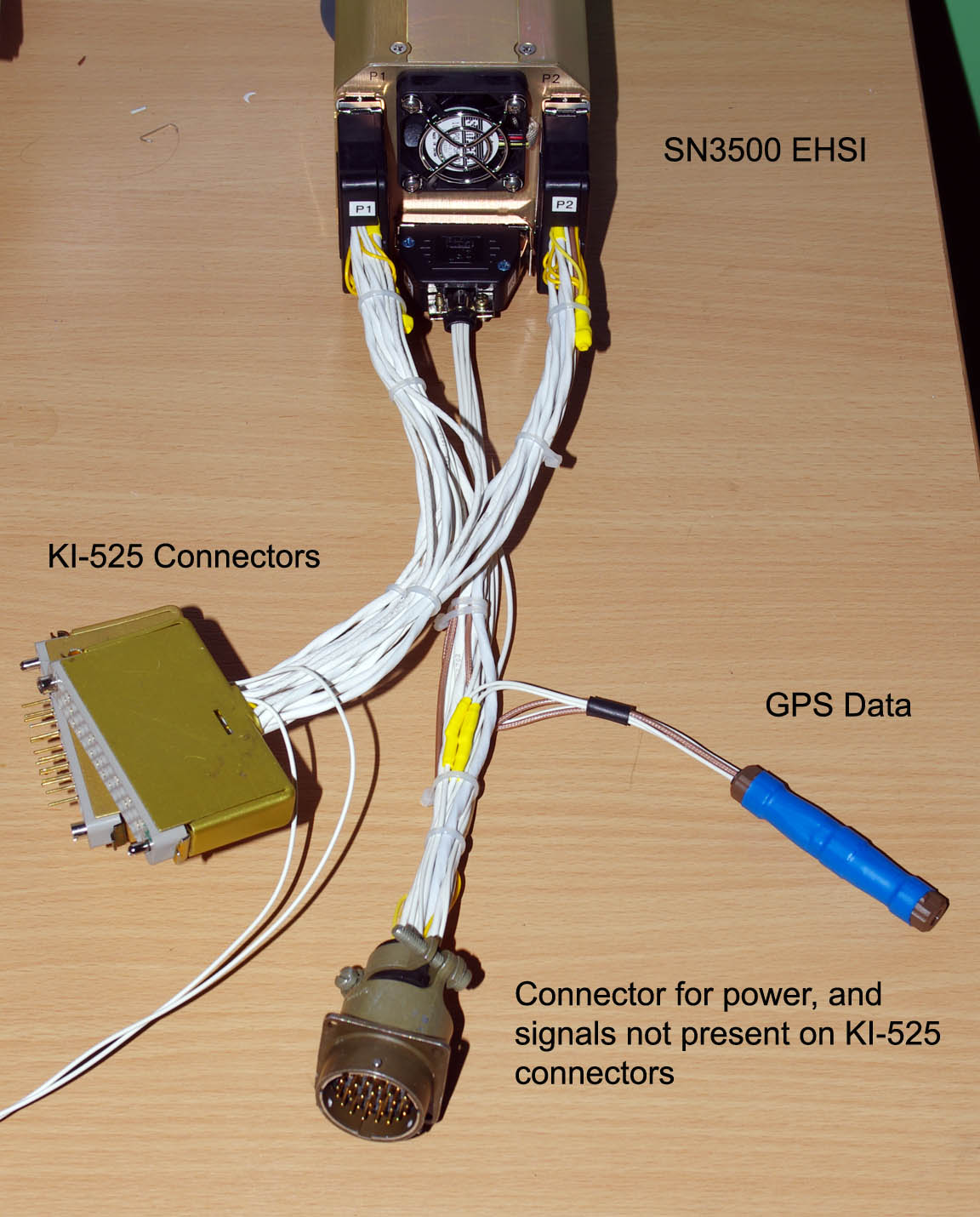
The schematic of the harness is in the PDF linked higher up above. The two single wires connect to the shields and go to airframe ground. It is important to ground cable shields to the airframe well because there is a lot of VHF and UHF radiation from the radio equipment. The important avionics analog signals (e.g. lateral and vertical deviations) are mostly differential anyway but that doesn't mean one can inject a lot of noise into these signals because a differential-input amplifier cannot reject common-mode noise which is outside its own bandwidth. The existing Socata wiring is to a very high standard already. The "GPS data" connector contains just a link to pass through the data from the KLN94 GPS; it was included to enable the data to be monitored with a protocol analyser in case of interoperability issues and it was removed in the final installation. The circular connector is a mil-spec 32-way Amphenol/Cannon type which also carries the +28V power to the EHSI.
It took about 1 day to make up the conversion harness; very slowly and double-checking every wire, and then buzzing the whole lot through. This represents a considerable time saving over doing this wiring inside the aircraft which is what one would have to do for a directly wired-in instrument; even more so when considering the 1k and 200R dummy load resistors which were conveniently located inside the harness. The DB connector shells are almost too tight for the amount of cabling; the traditional solution in the avionics business is to run just the unshielded wires into the shell and terminate all the shields outside of it.
Bringing in the various signals from around the aircraft to the circular connector took another 2 days; much of that time was spent looking for the relevant wires and for convenient places to splice into them, and do so without bodging it. The most time consuming part was expected to be picking up the GPS RS232 flight plan data and the stormscope RS232 data. The GPS wire does not go outside the centre avionics stack (unless it is a very late model TB20GT with this Shadin Microflo fuel totaliser instrument which requires the GPS data) but about 6 years ago I had a GTX330 transponder installed on which I requested automatic AIR/GND switching using the GPS ground speed. Unfortunately, this feature never worked (the KLN94-GTX330 connection is shown in the GTX330 IM but as usual both Garmin and Honeywell washed their hands of it) but the wire remained, and was easily accessible behind the GTX330. I was aware that the original GTX330 installer was a cowboy because I had to hoover out a pile of metal cuttings behind the panel; what I didn't know was that they also bodged the interconnection; firstly they avoided passing the wire through any of the centre stack bulkhead connectors and secondly they left some unused "live" wires tucked behind a metal bracket, with no effort made to insulate the ends. The stormscope data was picked up easily near the GTX330, where it passes on its way to the WX500 in the luggage compartment, via the RH side of the cockpit.
The NAV1 and NAV2 composite signals were easily picked up on the back of the switch which selects NAV1/NAV2 for the KI-229 RMI. Had this switch (installed on my request by Air Touring when the aircraft was new) or the KI-229 RMI not been there, the NAV1 composite signal would have been picked up from the input to the KN72, and the NAV2 composite signal from the back of the KI-204.
Connecting into the existing KI-525 connectors, and not bothering with full functionality (CDI and autopilot drive) on NAV2 (no choice if using the SN3500 in Slave mode rather than the Master mode) saved a vast amount of wiring.
Component Documentation
Traceability documentation was obtained for all components in accordance with FAA regs. For the SN3500 this was an 8130-3 form.
Configuration and Testing
The SN3500 can be powered up on the bench, without any signals connected. It can be fully configured in that way too. Obviously it emits various error messages... I bench-ran it for several weeks.
The SN3500 config mode is entered by holding down two buttons through power-up. There is a lot to configure and considerable familiarity with avionics generally is required. Once in config mode, pressing the course pointer for 2 seconds toggles the SN3500 between the config menus and normal operation; a very slick feature. The following screenshots show the various config screens and their final settings [update; ADF i/p is sin/cos]
1 2 3 4 5 6 7 8 9 10 11 12 13 14 15
The conversion harness enables the SN3500 to be tested out of the aircraft which is a big help
The wiring worked first time with two exceptions:
(1) The glideslope signals (E/B on KI-525 P2) had to be reversed. I did not spend much time investigating whether this was a SN3500 IM documentation error, a SN3500 software error, a KI-525 HSI documentation error, or something else. This kind of thing happens frequently and most avionics installers would just swap the wires without saying anything to anybody. The reversal was done inside the conversion harness so as to not affect a possible reinstallation of the original HSI. Update 12/2013: this turned out to be an error on the one page in the SN3500 IM. The rest of the IM is correct. The IM was corrected mid-2013.
(2) The OBS SIN signal from the SN3500 to the KLN94 had to be rewired, with P2/pin8 going to the KI-525 P2/pin "e". The Sandel drawing was just a bit "too generic" in these areas. Unfortunately, this fix broke the feed of the OBS SIN/COS signals to the KN72 which prevented autopilot tracking of a VOR radial. Explanation: the KFC225 autopilot is driven from the HSI terminals which are in turn driven - laterally - by the KN72 (for LOC/VOR) or by the KLN94 (for GPS) and - vertically (for GS) by the KX155A NAV1 receiver. While the SN3500 contains its own composite signal decoder and does not need the KN72, the KFC225 still needs the KN72 for its lateral deviations in LOC/VOR mode. And, in the VOR mode, the KN72 needs correct OBS signals from the SN3500's course pointer, because with a VOR the lateral deviation is obviously OBS dependent. Reconciling the SN3500 KN72 nav interconnect requirements with the KLN94 getting the right signals, via the old HSI connectors, without having to rewire the KN72 resolver inputs to match, took a bit of working out. Clearly "somebody" has been "at it" in the (or this particular) TB20GT, and in a typical avionics installer tradition swapped the wires around until the HSI worked but without much understanding of why. There is also more than one way to wire-up a resolver... Another hint that somebody has been here before is here. Even if this issue had not been fixed, the SN3500 would display the correct CDI presentation in all cases because it is decoding the NAV1 composite signal which does not involve the KN72. And flying a LOC/ILS with the autopilot - obviously vital - would work fine because the KN72 does not need OBS resolver signals in LOC mode. Update 1/2013: the KN72 was removed and the KFC225 is now driven from the SN3500's P2 output, in VOR/LOC mode only; in GPS mode it remains driven from the KLN94. Now everything works as it should. The wiring of this modification was done by connecting the P2 lateral out and lateral flag signals (4 wires) to the corresponding KN72 output wires and then removing the KN72, and the four wires plus shield pass through a dedicated connector which would be unplugged if the KI525+KN72 were reinstalled. Given the hassle of getting the KN72 to work in VOR mode with the SN3500's resolver outputs, I would recommend anybody installing a SN3500 to do it this way and ditch the KN72 immediately.
To get the SN3500's course pointer to show correctly on the KLN94, the SN3500's OBS output (sin/cos) had to be adjusted by about 60 degrees. It is highly likely that this was merely compensating for config in the KLN94 to fix an issue elsewhere (see the VOR/KN72 notes above), but I did not want to mess with the KLN94 config, in case of a KI-525 reinstall. There is a similar adjustment in the KLN94 (accessible in the installer pages) which I left alone to support the KI-525 reinstall option. The eventual bearing error was a maximum of 1 degree all the way round the compass; an astonishing accuracy which shows one of the advantages of an electronic instrument. The 60 degree error probably results from somebody having swapped both the resolver rotor wires (a 180 degree error) and two stator wires (a 120 degree error) on the KN72 or the HSI, and then had to adjust the KLN94 OBS calibration to make that read correctly.
No lateral or vertical deviations needed to be adjusted anywhere. The KFC225 flight director, driven from the SN3500 heading error signal, was spot on - undoubtedly because the KI-256 horizon (which supplies the KFC225 with roll and pitch data) is a Mod 11 unit which has buffered outputs. Note that the flight director doesn't indicate correctly unless the horizon is erected, with an electric vacuum pump. ILS deviations were spot on also.
The fluxgate magnetometer compass (KMT-112) adjustment which is done in the SN3500 turned out to be very close. The adjustment ("compass swinging") was very easy: turn the aircraft onto each of the four cardinals and adjust a value in one of the diagnostic pages. The resolution is 0.1 degree which is way closer than anybody can hold and read a reference compass.
The most amazing discovery was that the SN3500 OBS mode actually works with the KLN94! This was contrary to what everybody I had spoken to said, suggested, indicated, or implied would be the case with the KLN94. Evidently, years ago, some programmer at Sandel sat down with a KLN94 and took care to do it just right. The SN3500 detects when the KLN94 is in the OBS mode by looking for the "OBS" flag in the RS232 flight plan data, and not only disables CP auto-slew but also displays the correct bearing line to the active waypoint. The same bearing line also shows on the KMD550 MFD. This functionality is perfect.
I was able to confirm that the external OBS mode control (via P1/pin15) does not work (or does not work when the selected GPS type is a KLN94) but it didn't matter anymore.
How (or if) this works with a Garmin GNSx30/W GPS is a good question. I contacted several pilots with a GNSx30+SN3500 but none of them were able to clarify it, and I suspect none of them use their GPS for anything but straight enroute flight; possibly with GPS/RNAV approaches if in the USA. From the Socata switch diagram they use an external switch to control the OBS mode on a Garmin. More clues here and here from the 430W IM suggest that the external "OBS" switch is meant to be just a momentary button (pressing it is equivalent to pressing the Garmin's OBS button) and the SN3500's pin 15 should be driven from the Garmin's OBS-active annunciator output instead. The Garmin RS232 output data does not contain an OBS-active flag. The SN3500 IM is silent on this. One would really have to try it and see what it does; not a great state of affairs...
The GPS annunciators can be sent to the SN3500 via wires connected to the annunciator panel lamps, or the SN3500 can pick them out of the RS232 GPS flight plan data. The latter mode is slicker and saves wiring but predictably doesn't work until the KLN94 has finished its power-up sequence. Both modes ignore the TB20GT's annunciator TEST switch; this is obvious when you look at the schematic. I left the wires in place but used the RS232 mode.
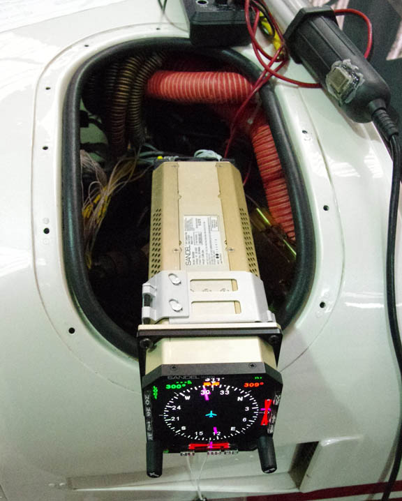
Instrument Install
Installing the SN3500 using the supplied clamp is straightforward. The four existing screw holes in the TB20 panel need considerable opening-out with a needle file (a hoover must be run behind each hole throughout to avoid getting metal filings into the lubricated yoke tube bearings) and the two clamp tightening screws need to be tightened to a suprising degree to hold the instrument securely. The SN3500 is also about 50mm longer than the KI-525 and this leaves only about 50mm between its back end and the TB20 window when the LH pilot instrument panel is tilted back for access
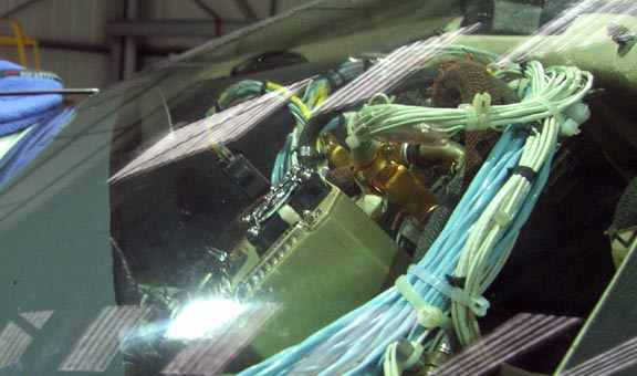
With the supplied DB15 and DB44 connectors and shells, there is no way the panel can be tilted as shown without the connectors being disconnected first, or without the SN3500 being loosened in its mounting clamp and moved partially out of the panel. One might possibly get away with it if using shells with a right-angle cable entry. Positronic appear to make these - see page 21 here.
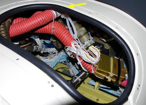
The conversion harness does fit but is tight. Obviously, it must be well secured so it does not fall onto the controls. The windscreen demisting hose attachment point (pointed to by the yellow arrow) is very sturdy and comes in very handy...
The Socata sheet metal trim had to be cut away underneath the SN3500
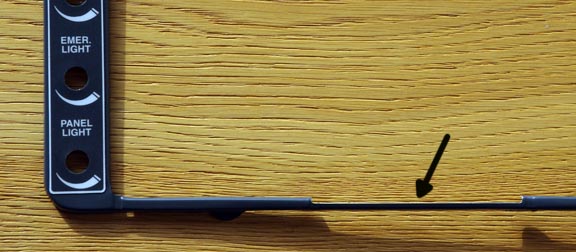
It was tempting to machine up a new trim out of solid 5mm aluminium... those trims are the one tacky item in the TB20GT cockpit.
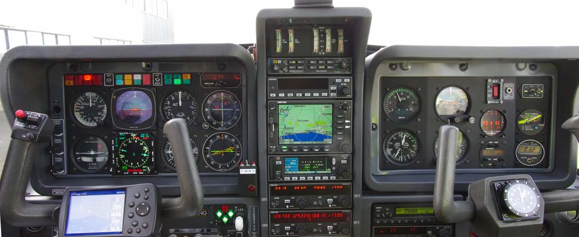
The finished job looks excellent
Variable Backlight
This is available on the LED-backlit instrument with firmware v4.03 or later.
The SN3500 variable illumination works perfectly if the manual adjustment is used (pressing the M button alone pops up the adjustment feature).
The external (instrument panel lighting bus) dimming feature did not work well. The lowest brightness setting achievable on the SN3500 is certainly dim enough for the darkest night, which is a good start because an instrument which does not dim far enough is a serious problem, but as the panel illumination is increased the SN3500 rapidly becomes too bright relative to the rest of the panel.
At a 24V supply, the TB20GT lighting bus voltage adjusts from 13.7V to 21.1V. For the TB20/21 GT, the schematic of the dimmer is here and it's a reasonable design. However, the pre-GT aircraft use a primitive design which is essentially constant current generator whose output voltage will depend on the total lamp load, and there is likely to be a significant temperature dependence. It also contains a serious design error in that the total lamp current passes through the tiny switch on the back of the dimmer pot, whose current rating is exceeded by at least 10x (the GT version uses relays to switch the lamp current). There is an adjustment in the SN3500 config for the voltage at which the display achieves its lowest brightness but there is no adjustment for the slope of the transfer function.
The manual brightness adjustment is partly retained even if external dimming is enabled, and is used to set the actual brightness at the lowest control voltage; this is important for flying on proper dark nights.
To some degree, one can combine the manual adjustment with the min-brightness voltage setting in the configuration, to get an acceptable automatic solution, but as the external dimming feature was introduced only recently, the whole behaviour is mostly undocumented.
I had also tested the SN3500 with a 50k pot (connected between GND and the positive supply) driving the brightness control input and that worked fine.
Update 12/2012: There is some strange behaviour in the SN3500 in that if it is powered up with the dimmer voltage input at some particular level, or maybe if it is powered up with the input seeing a specific transition, the EHSI display is totally blank and it looks like a dead instrument. It is fixed by turning up the TB20 brightness pot up/down; the EHSI comes to life immediately. I can't say whether this is a TB20-specific issue, and it's happened only a few times in 2 years.
Flight Performance
Before any flight, the installation was completely checked by an avionics technician with an IFR 4000 tester. The 337 was signed off by an A&P/IA and sent off to the FAA in Oklahoma.
The SN3500 LED-backlit display is perfectly visible under all lighting conditions including direct sunlight and does not appear to return the reflections typical with glass instruments
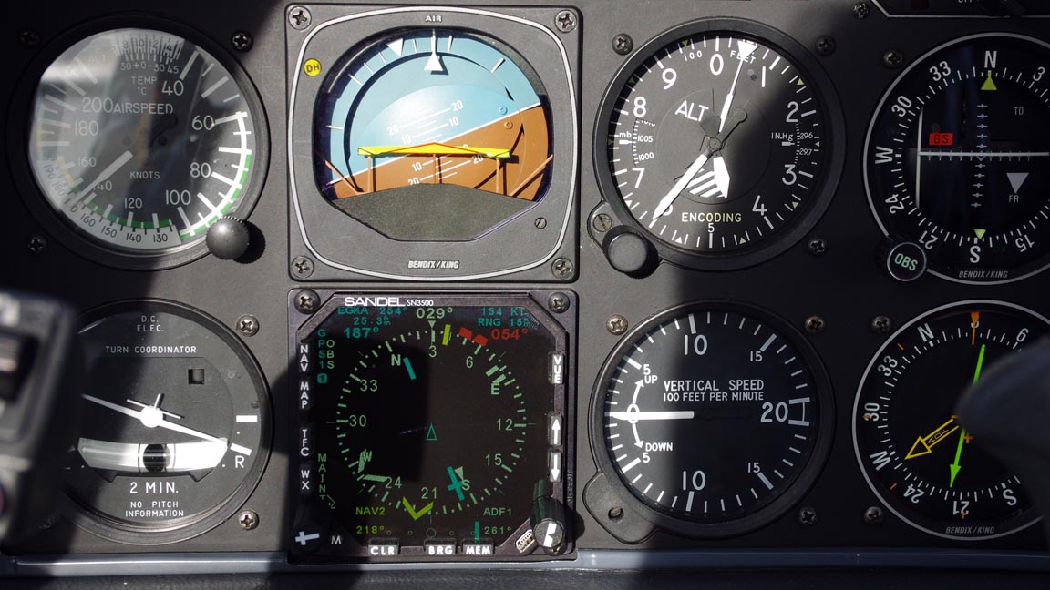
The above pic also shows the KI-229 RMI in the bottom RH corner, showing the ADF and the NAV2 VOR. The SN3500 is showing two bearing (RMI-style) pointers; also showing the ADF and the NAV2 VOR. As one would expect given that both come from the same sources, they correspond exactly.
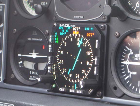
The current-model SN3500 display has an excellent viewing angle. This pic shows the right hand pilot view
As noted earlier, the OBS mode works perfectly. This is flying an NDB/DME approach, using the GPS OBS mode
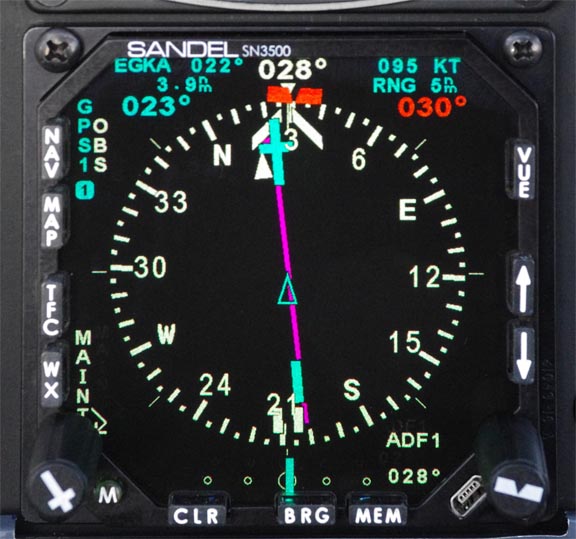
The KLN94 was manually set to 0.3nm full-scale. The magenta line shows the GPS track. The ADF pointer is pointing slightly off to the right, which is (perhaps suprisingly) actually correct because the NDB is to the right of the runway.
Autopilot behaviour is correct, including when flying with the CP auto-slew feature. In NAV mode, you can load a DCT to a waypoint, the CP swings around to point to the waypoint, and the aircraft simply turns directly to the waypoint. This is how it should work... Localiser intercepts are accurate, despite the KFC225 autopilot being driven from the KN72 and not from the SN3500's CDI. The LOC null adjustment remains in the KN72. However, the KFC225 "feature" whereby the lateral HSI deviation needs to be at least 3 divisions before NAV can be selected (otherwise the KFC225 does not fly an intercept but instead immediately transitions to a gradually converging parallel track) remains. For several years, Honeywell denied any knowledge of this "feature". Update 1/2013: the KN72 was removed and the KFC225 is now driven from the SN3500's P2 output, in VOR/LOC mode only; in GPS mode it remains driven from the KLN94. There is no longer any LOC null adjustment because the SN3500 decides the NAV1 composite signal very accurately.
Performance in turns: This was one of the big initial questions in this project, and nobody knew the answers...
Traditionally, and in this installation, an autopilot tracking a GPS track works by using the HSI course pointer as the "heading" and then uses the HSI lateral deviation to fine-tune this heading, to adjust for wind drift etc. With a mechanical HSI, the pilot turns the course pointer to the new (annunciated) track, at each waypoint. With an EHSI, the CP auto-slews and the autopilot turn is thus automatic. Obviously, the resulting turn performance will depend partly on exactly when the EHSI turns its CP.
A simplified diagram of the finished installation is below. Except for the SN3500's analog (P2) outputs, which were not used in this installation, and the SN3500 needing the RS232 flight plan data, this diagram is essentially identical for the old KI-525 HSI
When the KLN94 reaches a new waypoint, it emits the new flight plan data in the RS232 data stream and shortly afterwards updates its lateral deviation outputs to steer the autopilot to the new bearing. The SN3500 course pointer is driven from the decoded RS232 flight plan data, and rotates to the new bearing slightly ahead of the turn. The CP always rotates at the same speed, which is fast but well chosen to make the rotation clearly visible.
All significant-size turns are flown at Rate 1 (actually the KFC225, being attitude-controlled, turns at about 21 degrees of bank which is about Rate 1 at 140kt) so what matters for accurate turns is the point at which the turn is commenced.
The point at which the KLN94 generates the new lateral outputs is undocumented (and I could not get anything out of Honeywell) but it is not the same moment that the "waypoint" annunciator starts flashing, which usually happens earlier. The KLN94 has a feature called Turn Anticipation which can be enabled or disabled. With TA enabled, the KLN94 emits the new outputs a certain time before the waypoint would be reached. This time varies according to how sharp the turn is. For turns of about 60 degrees or more, it happens approximately 35 seconds before the waypoint (this can be measured from the tracks below which were flown in the easterly direction at a GS of about 160kt). For turns of just a few degrees, it happens only a few seconds before the waypoint would be reached. With TA disabled, the KLN94 emits it at the waypoint. Obviously, the latter is guaranteed to result in an overshoot.
Unfortunately, the turn anticipation does not work well for larger turns. The KLN94 starts those much too early. In the following pics, the two blue lines represent a 90-degree turn (programmed in the GPS using a track fragment of EGKA-SFD-WESUL). The red line is the actual track. The wind was about 330/020
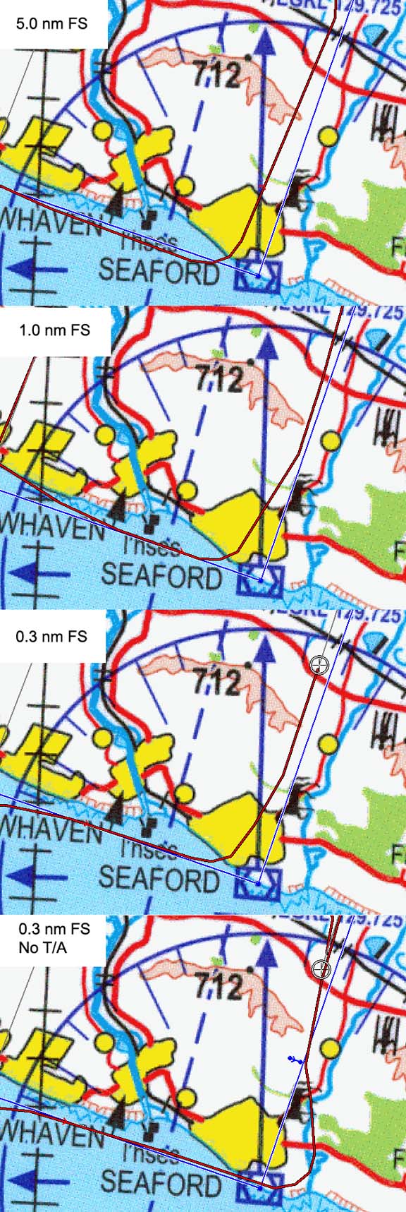
One can work out the likely thinking behind the 35-sec advance: it is about right for a 90-degree turn at Rate 1, with a bit of a lead-in and lead-out at a smaller turn rate, and smaller turns are much less critical anyway. Unfortunately, somebody messed up because it's obvious that the geometry is plain wrong and it should be about 20 secs if the exit track of the turn is to be aligned with the new track. The 35-sec advance is not dependent on the full-scale sensitivity of the KLN94 which can be set manually to 5.0, 1.0 or 0.3nm, or which varies automatically through 1.0 to 0.3nm when flying a GPS/RNAV approach loaded from the database. The pics show that increasing the GPS sensitivity does not yield a more "intelligent" turn, although of course the general tracking before and after the turn is most accurate at 0.3nm FS.
The last pic above shows the performance with KLN94 turn anticipation disabled. The result is messy for a 90-degree turn but most pilots would never notice on normal enroute flight with small turns.
One wonders whether driving the autopilot from the SN3500's P2 (FSC) autopilot outputs would produce a better turn behaviour, but it is highly unlikely because as far as I have been able to find out, the P2 outputs just echo the CDI presentation. 1/2013: Sandel are now offering a "roll steering" option, $1000, but unfortunately it can be used only with a GPS feeding the SN3500 via ARINC429, not RS232.
However, to put the above performance into perspective, the worst-case undershoot, in zero wind, at 140kt GS, is about 0.4nm. There is no doubt that this level of performance is perfectly adequate for flying the published T-shaped GPS/RNAV approaches. Even the big overshoot in the last case is about 1.0nm which would be barely noticeable in most enroute flight. And in normal enroute flight, with small turns, the KLN94 advances the RS232 output by only a few seconds and the turns are perfect.
A flight test of a GPS/RNAV approach, flown at 130kt on a light-wind day, shows the usual undershoot on the 90-degree turn, but accurate enough tracking, especially by the time the KA20F FAF is reached
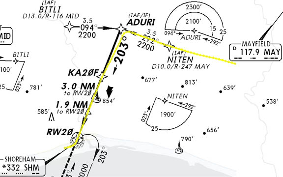
Generally, I find that the 90-degree turn is flown more accurately at higher speeds, and 140kt is fine and gives plenty of time to slow down for the FAF.
On GPS/RNAV approaches, the GPS full-scale sensitivity changes automatically from 5.0nm to 1.0nm and finally, about 2nm before the FAF, to 0.3nm. Note that the KFC225 autopilot is used in the NAV mode in this case, not the APR mode which is used for an ILS.
I fly enroute with the GPS at 1.0nm FS, and switch to 0.3nm FS for the final approach track of a "GPS overlay" approach. I never use the 5.0nm FS setting.
The only potential way to improve things would be to install the analog KLN94-KFC225 roll steering feature described earlier, but its behaviour is undocumented and I have not found anybody who knows anything about it - including TB20 pilots who believe they have it installed... It would also be largely wasted because the KLN94 does not have database support - in Europe - for RNAV SIDs/STARs, or any curved segments.
When flying a LOC/ILS approach, the SN3500 course pointer must be set to the inbound track and the aircraft heading needs to be plausible. With a mechanical HSI, the CP can be pointing backwards (except (a) doing so will mess up situational awareness and (b) any autopilot will not be driven correctly) but if the SN3500 CP is pointing backwards when a localiser signal is received then the lateral deviations will be reversed and the SN3500 shows "BC" i.e. it assumes you are flying a back course approach. Putting it another way, when flying outbound on a procedural ILS, expect to see indications appropriate to a BC approach, and disregard them as appropriate. There are no BC approaches in Europe. This pic shows a flight where the aircraft is flying almost parallel to the localiser (runway 21) but outbound, with the SN3500 showing the correct deviation bar indication for a BC approach. The "back course" mode was never pilot-selected; the "BC" appears automatically
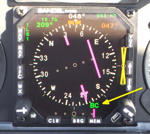
The "BC auto detect" mode also disables any glideslope indications, as shown above, which is correct because a BC approach is a LOC-only approach. When you turn around onto the localiser, so the aircraft heading is reasonably close to the course pointer and the runway inbound track, the "BC" disappears and the deviation bar indicates correctly for a standard localiser. This all makes sense but would suprise someone used to using mechanical instruments in a sloppy manner, showing plausible localiser and glideslope indications regardless of which way the aircraft is pointing.
The GS auto-suppression also stops most spurious GS indications, which is very different to mechanical instruments which will happily show a valid GS without a valid LOC - something which every pilot will have routinely noticed when flying in the vicinity of various airports. It also makes it impossible to test the system with cheap avionics testers that emit either a GS or a LOC.
The above pic also shows the DME reading (10.7D). A Slave-mode SN3500, if correctly wired to the KN-63 DME to detect the NAV1/NAV2 switch selection, will display the figure there only if NAV1 is selected on the KDI-572 DME indicator. This acts as an added safeguard against flying an ILS with the ILS frequency correctly set on the NAV1 receiver but the DME itself set to display from the NAV2 receiver. However, this error would be noticed by checking the morse code ident for the DME.
Conclusion
Was it worth doing? Definitely. The SN3500 is a great piece of equipment which is a pleasure to fly with. The display in particular is stunning and better than any other piece of avionics I have ever seen.
I also hope this article is useful to pilots withing to upgrade their aircraft; particularly TB20GT pilots who can use the information directly.
Obviously, an aircraft owner without the facilities I have will need to use an avionics installer, but the documentation presented here should enable the installation to proceed much more smoothly and predictably, and with a much lower cost.
One of the most difficult and frustrating aspects of this project was what is best described as extraction, via an astonishing number of emails, of concise and unambiguous information from sources which are presumably used to dealing only with avionics dealers/installers who have gone up the various learning curves at their customers' expense and who are happy to continue to do so. And, as described, some important interoperability questions were never answered pre-installation. The SN3500 installation manual could also be very substantially improved; many of the configuration options are ambiguous or undocumented and the installer is expected to "play" with them until it works.
The problem is that not all installers have the required degree of understanding of avionics interfaces; a situation made worse by the vast majority of them not being pilots. This Aviation Consumer review of the SN3500 (somewhat out of date; describes the older pre-LED version) is a fine example of an installation done by a totally inept installer who did not do even the most basic avionics tests prior to customer delivery; this is not unusual and I have had avionics work done (by well known firms) which simply did not work. I found plenty of people who install this equipment but most of them just follow the installation manuals. I found very few people who truly understand the subject but all of them work in the business and in general would not be expected to provide support for a customer-led design of this type.
Notes for Installers
If someone wishes to follow the procedure detailed in this article, on a very similar aircraft, they should consider the following:
1) If installing on an N-reg aircraft based outside the USA, you need to sort out your certification route before you start. The FAA FSDO route may or may not be available and you may have to use the DER/8110-3/337 route, without an AFMS. I may be able to suggest some contacts.
2) Remove the KN72 converter, leaving its connector harness in place, and wire up the SN3500 P2 (FSC) lateral deviation outputs to the corresponding KN72 connector terminals. That will then feed the SN3500's P2 lateral deviation to the autopilot, while preserving the KI525 reinstall option (the KN72 will then have to be reinstalled too, of course). This is a very neat approach, which does away with the less than reliable KN72 box, ensures that the autopilot is laterally driven from exactly the same signal which is displayed on the SN3500, and enables autopilot tracking accuracy to benefit from future SN3500 firmware enhancements. The required 4 wires (plus ground) need to go via a separate connector which would be unplugged if the KI525+KN72 were reinstalled. I did this 1/2013 and it works great.
3) Try sourcing right-angle-cable-entry DB connector shells for the three SN3500 connectors. It may just enable the instrument panel to be tipped back without having to unplug the SN3500 connectors.
4) If you are installing a SN3500 in a TB20GT identical to mine (KLN94 etc) then you have zero risk on the functionality because you can do what I did (though I strongly recommend 2) above) and the only advantage of the conversion harness route is that it saves a lot of time messing around inside the aircraft.
Acknowledgement
I owe a BIG THANKS to all those people who helped me with information which
made this project possible. You know who you are ![]()
Update 1/2012
A year on... Everything is still working fine. Two minor issues did surface however:
The MEM button on the SN3500 has developed a fault: if it is pressed a little too hard, it sticks and the instrument becomes useless because the display rapidly flickers. The fix is to pull the button out, with fingers or pliers, and this releases the sticky switch. As the unit is out of warranty, I opened it up to see if it could be easily fixed. The offending switch is just a little PCB mounted switch like this which costs well under $1. Doing an instrument swap (under warranty) with the US vendor would cost about 500x that in shipping costs alone... I "fixed" it by machining a tiny "guard" which is glued in place with epoxy and which partly covers the MEM button so it cannot be operated accidentally. The switch is not hard to replace, and appears accessible. Most of the other switches are extremely easy to access. I never use the MEM button anyway; it gets used only in the 2-button sequence to enter the config mode. The internal build quality of the SN3500 is excellent. It is a sophisticated design which uses the Freescale MP8250 processor and a couple of Xilinx FPGAs. I have done a lot of Xilinx FPGA (and ASIC) design and I know this technology well. The design appears to date from about 2004.
When turning through two specific headings (090 CW or 270 ACW), the white compass arc turns red for 2-3 seconds, indicating an "invalid gyro" signal. This was not noticed for 6-9 months but was probably always present. I think most pilots would never notice it. I replaced the KG102A gyro with an overhauled unit, which didn't fix it, so I replaced the KMT112 fluxgate magnetometer with a new one, which didn't fix it either. This was a huge expenditure (a few thousand $) for no result, but these two devices were ~10 years old and they do eventually pack up. It appears that the SN3500 flags as "invalid heading" not just the obvious KG102A signal but also some below-some-threshold voltage level from the KMT112, and since the KMT112 output varies with the heading (perhaps dipping to a minimum on the cardinals) this just marginally pushes the SN3500 firmware (which decodes the heading by signal-processing the KMT112 waveforms) into indicating an invalid status. It doesn't affect its operation at all otherwise. To resolve this, I downloaded data logs from the unit (via USB, with software they supplied) and sent them to Sandel.
Update 5/2012
After a number of months, Sandel got around to looking at this. They asked for a video showing the fluxgate voltages displayed in one of the diagnostic screens, during the flight maneuvers which cause the above issue. It turned out that at the particular area I was flying in (in the vicinity of EGKA-EGMD) the earth's magnetic field declination happened to match the aircraft bank angle and the two fluxgate voltages both fell to zero. This was being incorrectly flagged as an invalid fluxgate signal. Sandel are implementing a firmware fix.
Update 12/2012
The aircraft has been updated with an Avidyne TAS605 traffic warning system, whose ARINC 429 output goes to both the KMD550 (whch had to have the KAC504 ARINC interface card fitted) and the SN3500. The SN3500 needed the software key to enable this functionality. The installer did a right mess of the installation but the finished system works great, with traffic displayed on both SN3500s (see below) and the KMD550. Each display device can set its own radius of interest.
Update 1/2013
The KN72 was removed and the KFC225 is now driven from the SN3500's P2 lateral FCS output. This changes the VOR/LOC mode only; in GPS mode it remains driven from the KLN94. It would be "more proper" to drive the KFC225 entirely (laterally) from the SN3500's lateral FCS output i.e. in both NAV and GPS modes, and this would enable the removal of one of the two big Northern Airborne relays (which switch a load of signals between NAV/GPS) but I can't see it would improve anything since the KFC225 already tracks GPS just fine. Also the KFC225 inputs are difficult - probably impossible without centre stack removal - to access and to separate-out from other wiring.
Sandel have done a firmware update which does roll steering, which would make this mod worth trying, but it works only with an ARINC429 GPS-SN3500 connection, not the RS232 connection used with the KLN94.
Update 6/2013 - 2nd SN3500, SG102 & MT102 Installation
An opportunity came up to buy another SN3500 and a SG102 AHRS gyro at a very good price, and these were installed. They were unused and current hardware versions but were not new, so I sent them to Sandel for a complete refurb, which was about $1000.
The SG102 and its MT102 fluxgate replace the old KG102A and the KMT112 fluxgate, and deliver heading data in both ARINC429 (used for the SN3500s and for the TAS605) and in X/Y/400Hz (used for the WX500 and the KMD550).
The SG102 was mounted on the old KG102A metalwork (which turned out to be already correctly levelled in pitch and roll) via an adaptor plate machined out of 10mm Tufnol
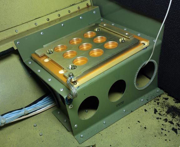
The large KG102A-compatible connector on the SG102 was not used:
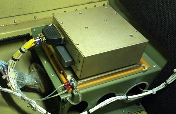
The Sandel MT102 fluxgate is the same size as the KMT112 fluxgate. The existing cabling was used, with the MT102 connector attached to the fluxgate end of it
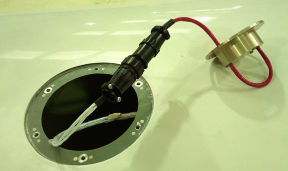
This shows the MT102 mounted in the circular Socata mounting frame
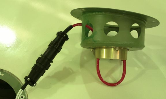
One of the holes in the side of the mounting frame had to be enlarged to get the MT102 connector through it.
The MT102 is secured with the three screws and is aligned with the arrow pointing reasonably accurately in the direction of travel
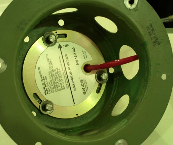
The heading calibration ("compass swing" in traditional aviation) is done with a laptop running the Sandel Windows program. The process involves moving the aircraft to point exactly on the four cardinal headings (which needs a person outside with the proper alignment compass) and pressing a button in the program, then repeating the process once more to get it more accurate.
However, before the heading calibration, the MT102 needs to be connected via a 50ft extension cable
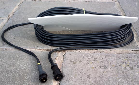
and removed from the aircraft by 50ft, while the system measures the magnetic field at that location. Sandel sell this cable but the drawing is provided and it is trivial to construct.
As the original SN3500 proved itself to be completely reliable, there was no need to maintain the KI525 HSI reinstallation option, so the temporary KI525-SN3500 conversion cable described earlier in this article was replaced with a complete new harness
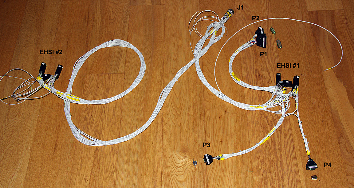
The new harness serves two main purposes: it is of the appropriate extra length to enable the LHS TB20 panel to tilt without having to disconnect anything (which is obviously desirable but often not the case with "rewired" TB aircraft, because it takes a bit extra effort), and it carries all the applicable signals to the RHS EHSI. It also incorporates extra connectors for future enhancements.
The LHS EHSI remains configured for Slave mode i.e. the NAV/GPS switch is still as it was and nothing changes there. That is also as per the original 337 field approval so I didn't want to change that. The only downside is that one cannot fly an ILS using NAV2; NAV1 only may be used. NAV2 is accessible as an RMI pointer only, not as a CDI deviation bar.
The RHS EHSI is configured for Master mode and its NAV button cycles through all possible lateral nav sources i.e. GPS NAV1 NAV2 and this delivers ILS capability on both NAV1 and NAV2. A glideslope relay is required for this because the SN3500 has only one set of GS inputs. There is no autopilot connection as that would force a new autopilot AFMS which would make it a Major alteration and a huge can of worms.
The new panel, with the RHS horizon and altimeter moved to their correct locations, looks outstanding
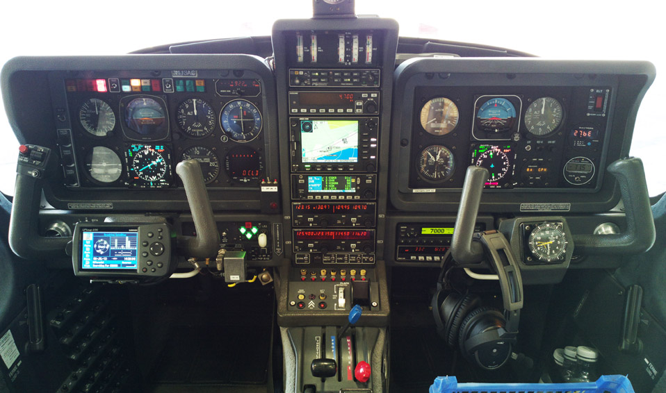
A toggle switch for each SN3500 selects its mode from the two options

The two modes are possible only with the SG102 which outputs pitch and roll on ARINC429.
LHS EHSI config 2 3 4 5 6 7 8 9 10 11 12 13 14 15 16
RHS EHSI config 2 3 4 5 6 7 8 9 10 11 12 13 14 15 16
The entire old KCS55 slaved compass system was sold on US Ebay for $2500. Somebody got good value there, as it included some spares I had on the shelf: two KMT112 fluxgates and two KI229 RMIs.
Future Plans
It looks like Europe will one day force PRNAV (RNAV1) compliance for enroute IFR. There are already many airports which publish only PRNAV SIDs and STARs but all of them ignore the requirement - they have to since most sub-airline aircraft are not PRNAV approved. However the enroute requirement is slowly creeping along... and while the KLN94 is fine for flying with the required accuracy (by a huge margin) will never be able to comply with the compliance documentation requirements.
More practically, LPV is coming, if very slowly...
The most practical current upgrade route using proven hardware is a Garmin GTN750 whose 6" height exactly replaces the KLN94/KMD550 in the vertical stack height. This would drive the two EHSIs using ARINC429 (the glideslope may have to be analog?). One would then use the LH SN3500's FCS outputs to drive the KFC225 autopilot, via the optional SN3500 roll steering software upgrade (which is just a $1000 unlock key) which is a neat solution because you get seamless ILS/LPV operation. The above cable has been prewired with extra connectors, for this upgrade. This is a photoshopped mockup with the GTN750
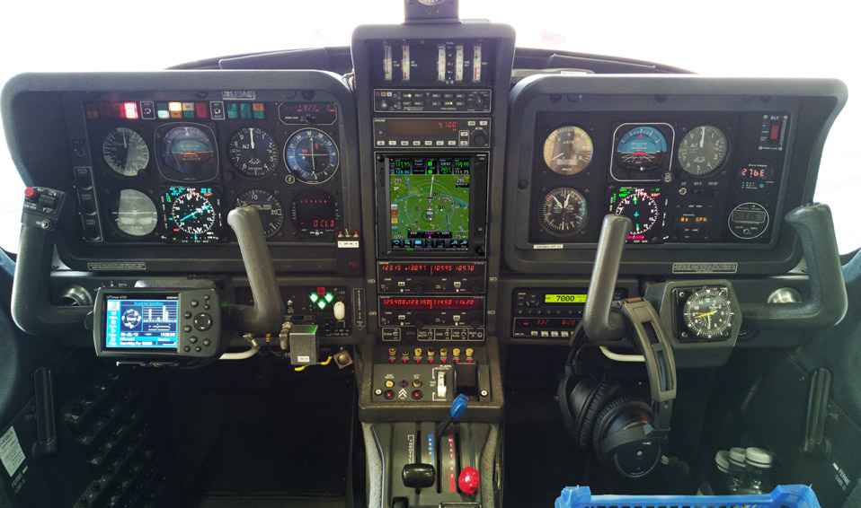
This would use the Garmin AML STC which delivers both PRNAV (RNAV 1) and LPV "paperwork compliance". Therefore, this installation would not require any FAA FSDO approval which is an important consideration for Europe based aircraft! However the FAA still operates its old 2005 position on PRNAV and the operator needs the PRNAV LoA from the FAA, which according to reports from the handful of European pilots with the stamina to go through this took about a year to come from the NY IFU, and nowadays (2015) is almost unobtainable.
One "problem" with the GTN750 route is that it leaves both KX1x5A radios in place so there are now 3 COM channels, which the existing intercom cannot handle. One solution is to install the Garmin GMA35 remotely controlled intercom (which can handle 3 channels) but this wastes a part of the GTN750 screen area for the intercom functions, and introduces a single point of failure for the intercom control. There is however another almost identical intercom model from PS which does 3 COM channels; it does only 2 NAV channels but that's OK.
Also I am not too keen on replacing my present GPS+MFD combination with a single box. The GTN750 can display all the same things but if you want to use it as an MFD, everything is several keystrokes away.
That leads to another and much more capable solution for PRNAV/LPV in the form of two Avidyne IFD540s which at 4.6" each would fit fine if both KX radios were removed (10" total space, leaving a 0.8" free strip at the bottom) and would deliver just 2 audio+nav sources for the intercom to deal with. Here is a photoshopped installation:
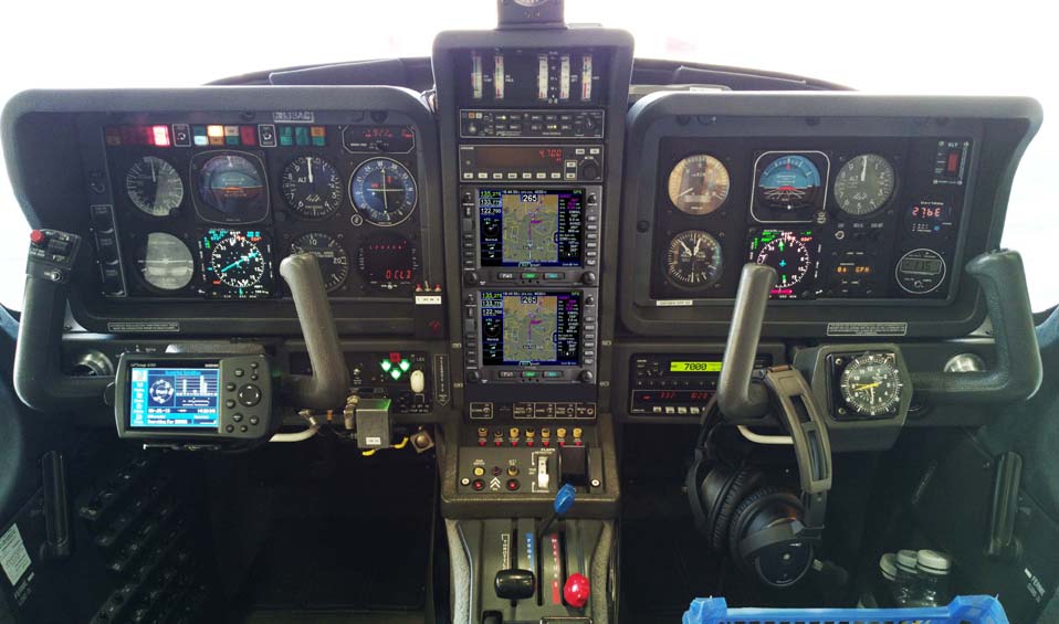
The IFD540 works much better than the GTN750. The user interface is more responsive, the touch screen is better, and it has some nice features which facilitate a rapid flight plan entry/modification using the knobs rather than the touch screen, which is advantageous in turbulence. European IFR in particular features ridiculously long routes and the IFD540 deals with them very nicely.
However, at time of writing (January 2015) the IFD540 has major problems. Avidyne didn't test it properly and it does not work in Europe, with the EGNOS (WAAS in the USA) system. Avidyne are sure to fix this eventually, along with a few other bugs e.g. an intermittent loss of GPS reception. I would not consider it until it was out in the market for at least a year. Even the GTN750 had a major recall in 2014 to fix a serious hardware defect, and hardware defects are a big problem because you need an official dealer's co-operation for processing the unit.
The 2xIFD540 option would be more expensive. Currently (1/2015) an IFD540 costs about $13000, which is a special discounted price. With import VAT at 20% that makes the installation best part of $40000.
There are issues with either the GTN750 or the IFD540 in that while the STC remains valid for an installation not done by an official dealer (notwithstanding bogus statements to the contrary when you ask the direct question) it appears very likely (from public statements of the companies) that they may try to wash their hands of the warranty if the installation was not done by an official dealer.
For a "self managed" installation which needs only an A&P/IA
to sign off the 337, plus a competent avionics guy to wire it all up, it is
possible to source these units without the installation included but it would
involve some subterfuge. They are available as hardware-only for Experimental/homebuilt
aircraft, but some evidence of the actual target aircraft may be needed ![]()
All of the above would be fully compatible with the 2 x SN3500 EHSIs and the FCS output of the LH EHSI would be used to drive the autopilot.
November 2015: According to avionics installers I know, the IFD540 is still being shipped with a > 100% defect rate i.e. every one has to be exchanged - because something on it doesn't work.
May 2025: The SG102 is not as reliable as it initially appeared. Sandel did an internal redesign because the original ADXRS613 yaw gyro chips because unavailable (actually ADI made another part which is identical, but the original design was an overkill) and ended up using another gyro chip (MAX21000) which was also discontinued c. 2015. More info here. So I make a point of keeping a spare SG102 on the shelf.
Documents
Sandel
SN3500 Installation Manual Rev K
Sandel
SN3500 Installation Manual Rev P
Sample AFMS Final
AFMS
Final 337
KCS-55 removal reference
KLN94 wiring diagram
KLN94 IM
KI-525 wiring diagram
KX155A NAV1 wiring diagram
WX500 wiring diagram
Switch/Indicator wiring diagram
KN63 wiring diagram
KR87 wiring diagram
COM2 wiring
KI204 composite VOR wiring
KI229 composite VOR wiring
Radio Master switch
Last edited 5th May 2025.
Any feedback, reports of dead links, corrections or suggestions much appreciated
Contact details

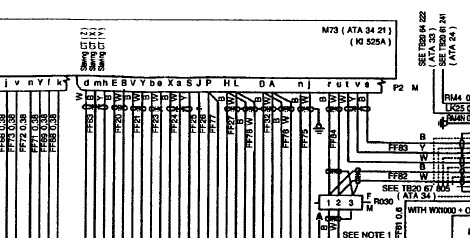
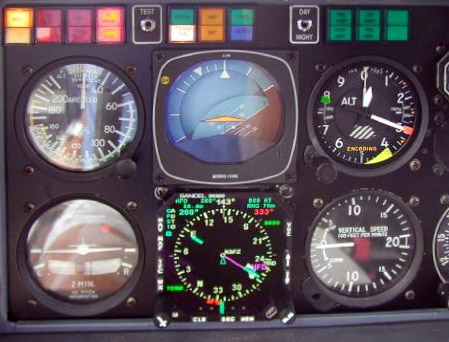
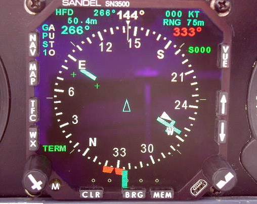
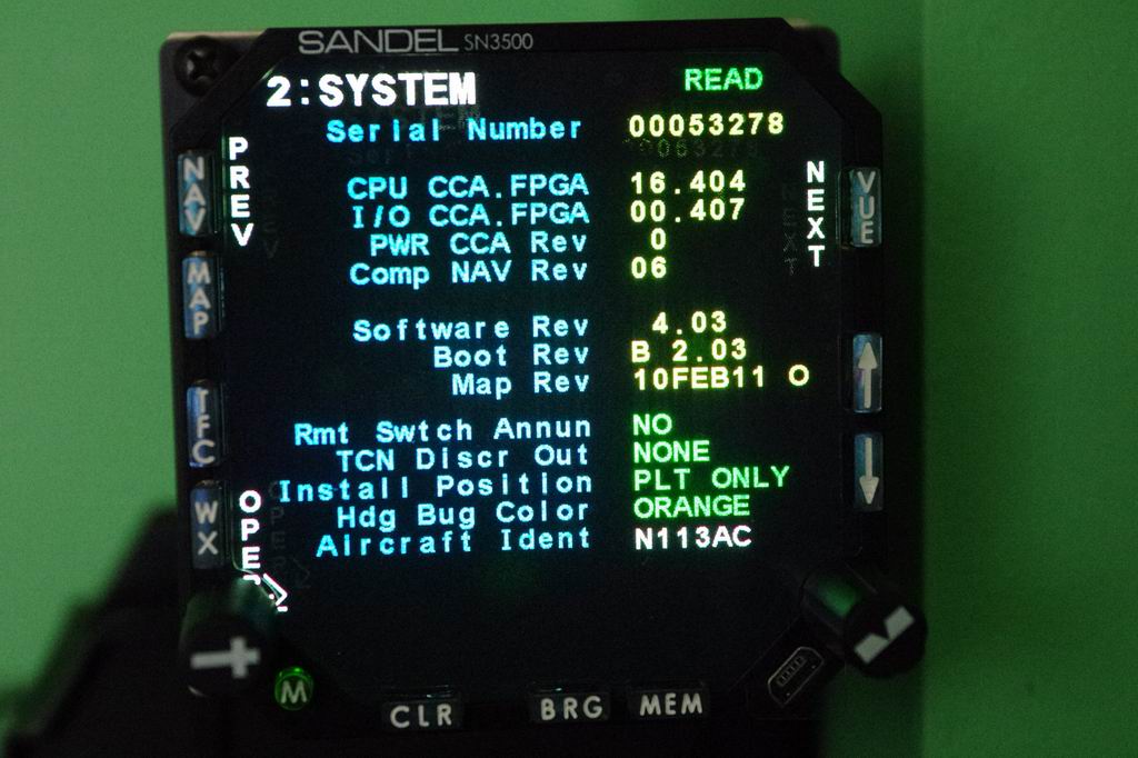
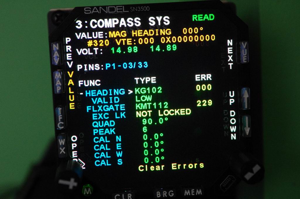
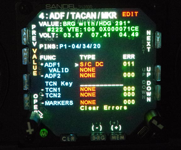
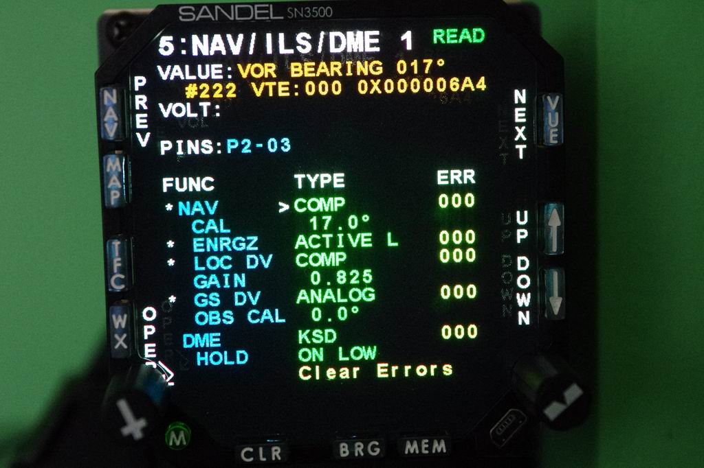
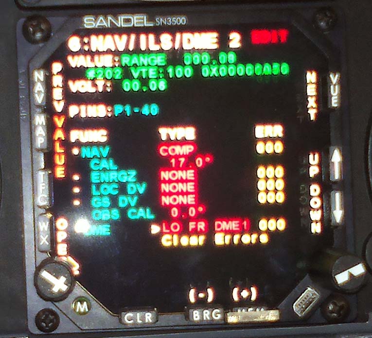
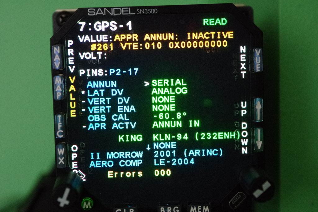
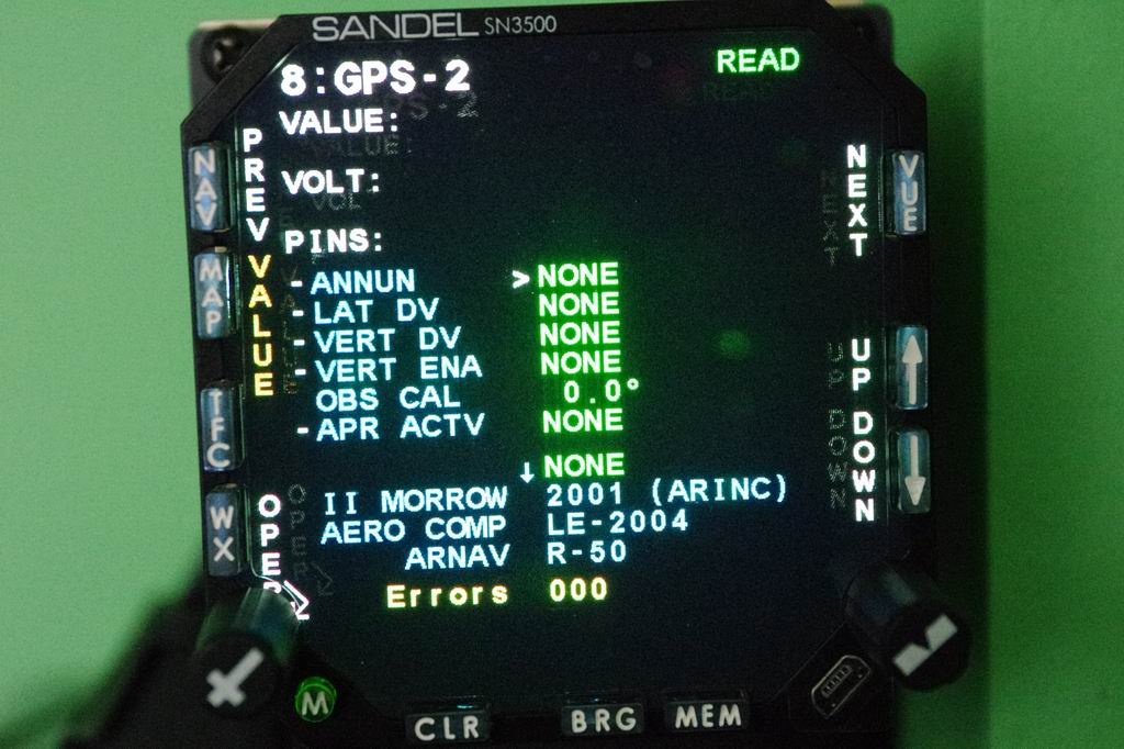
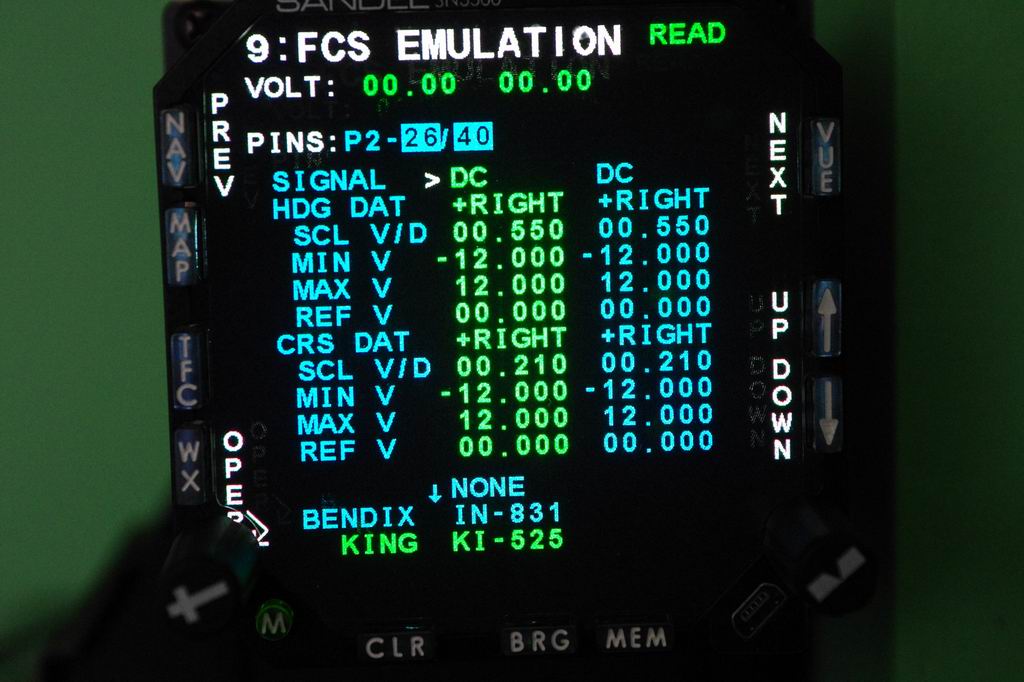
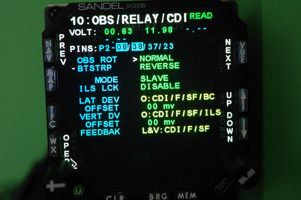
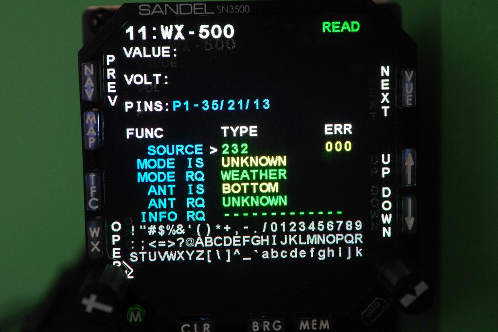
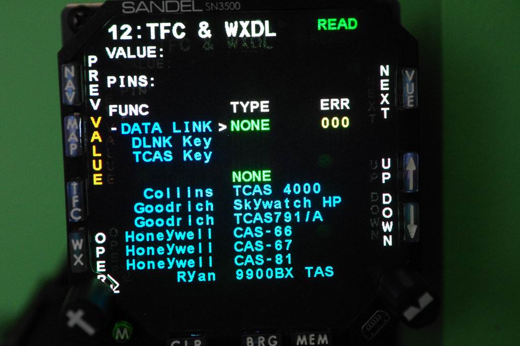
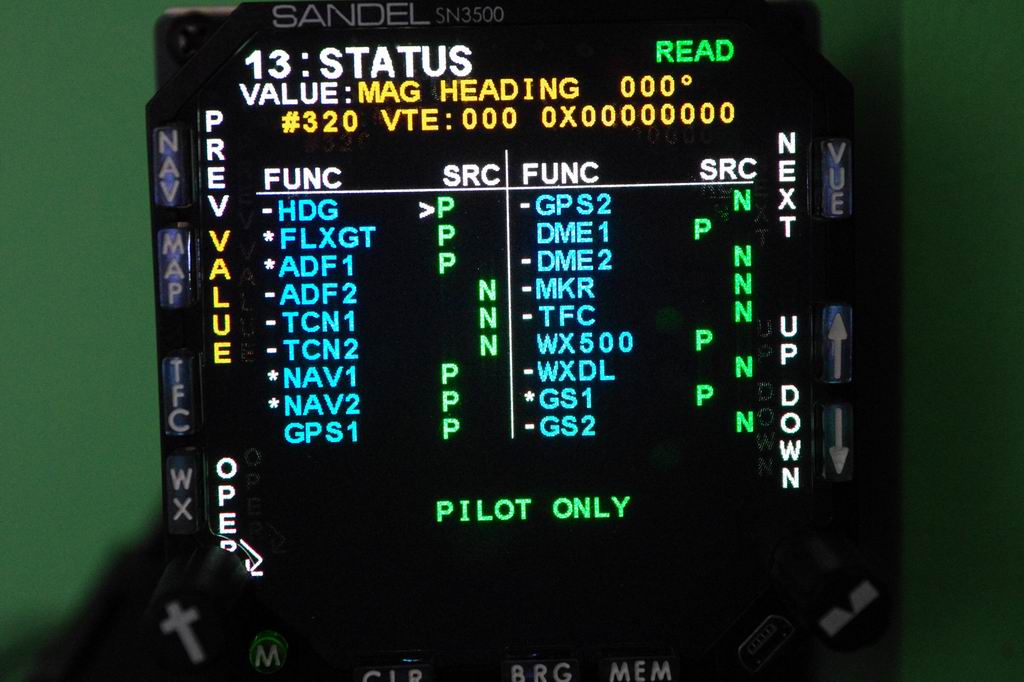
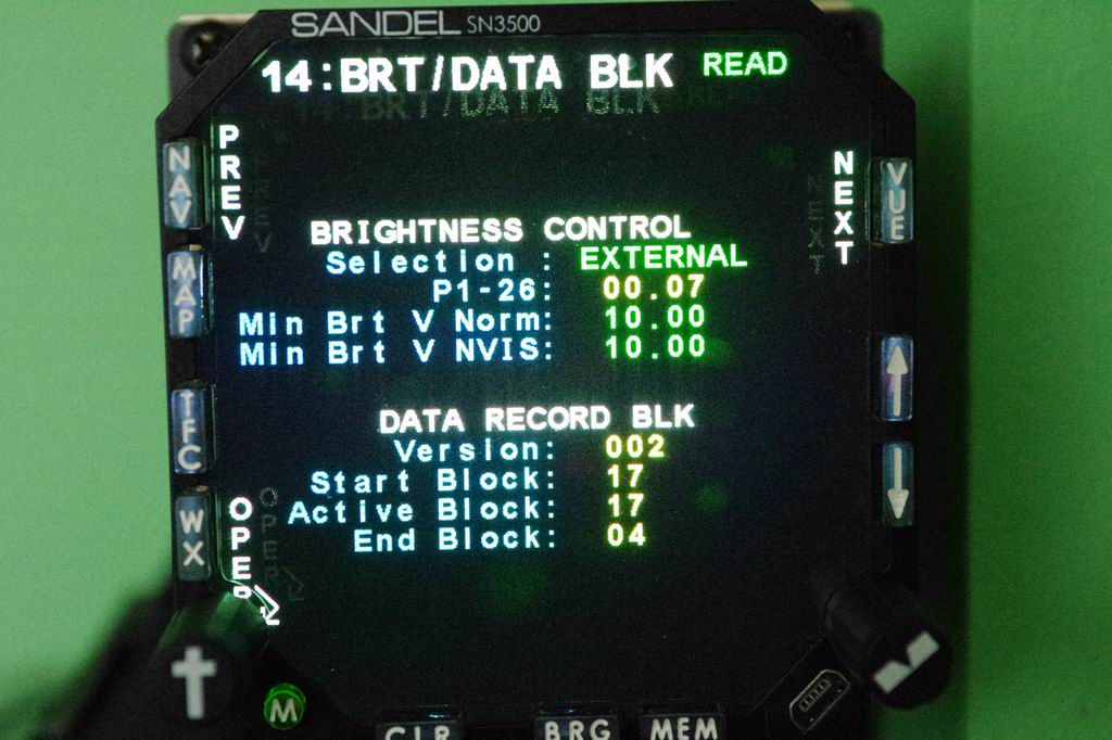
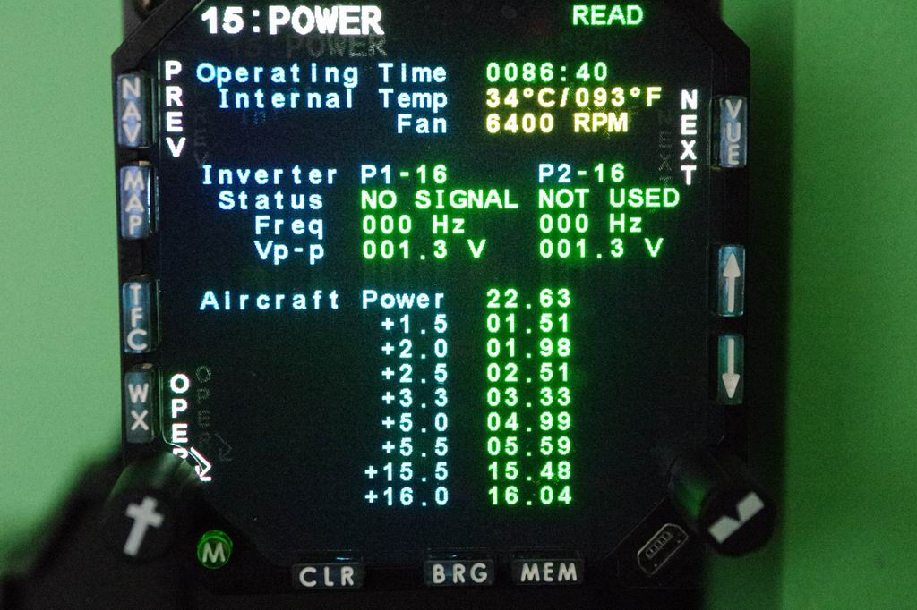
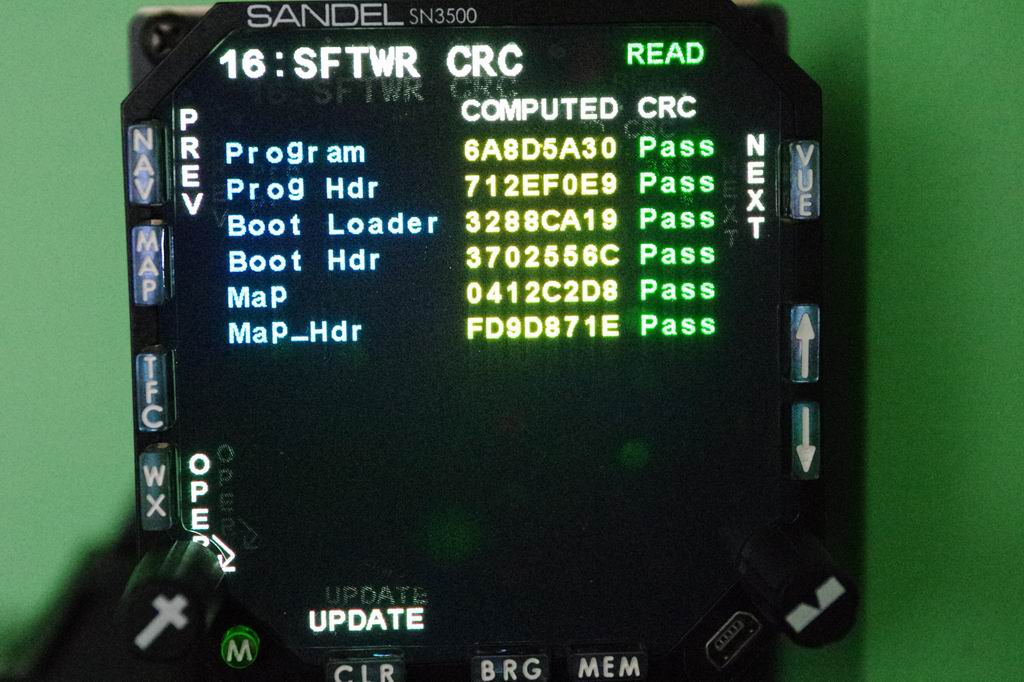
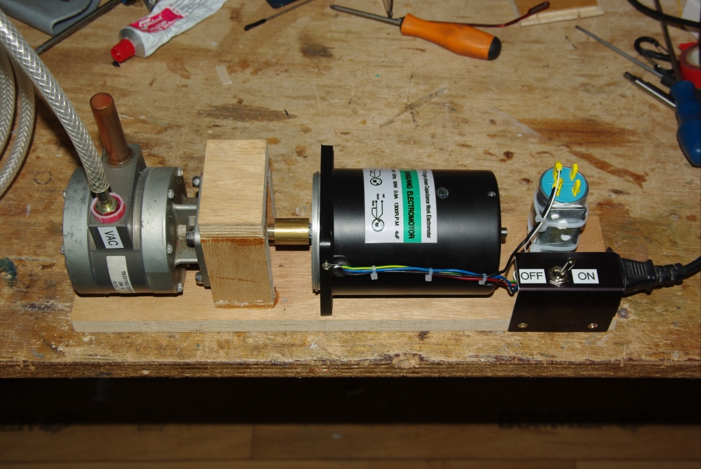
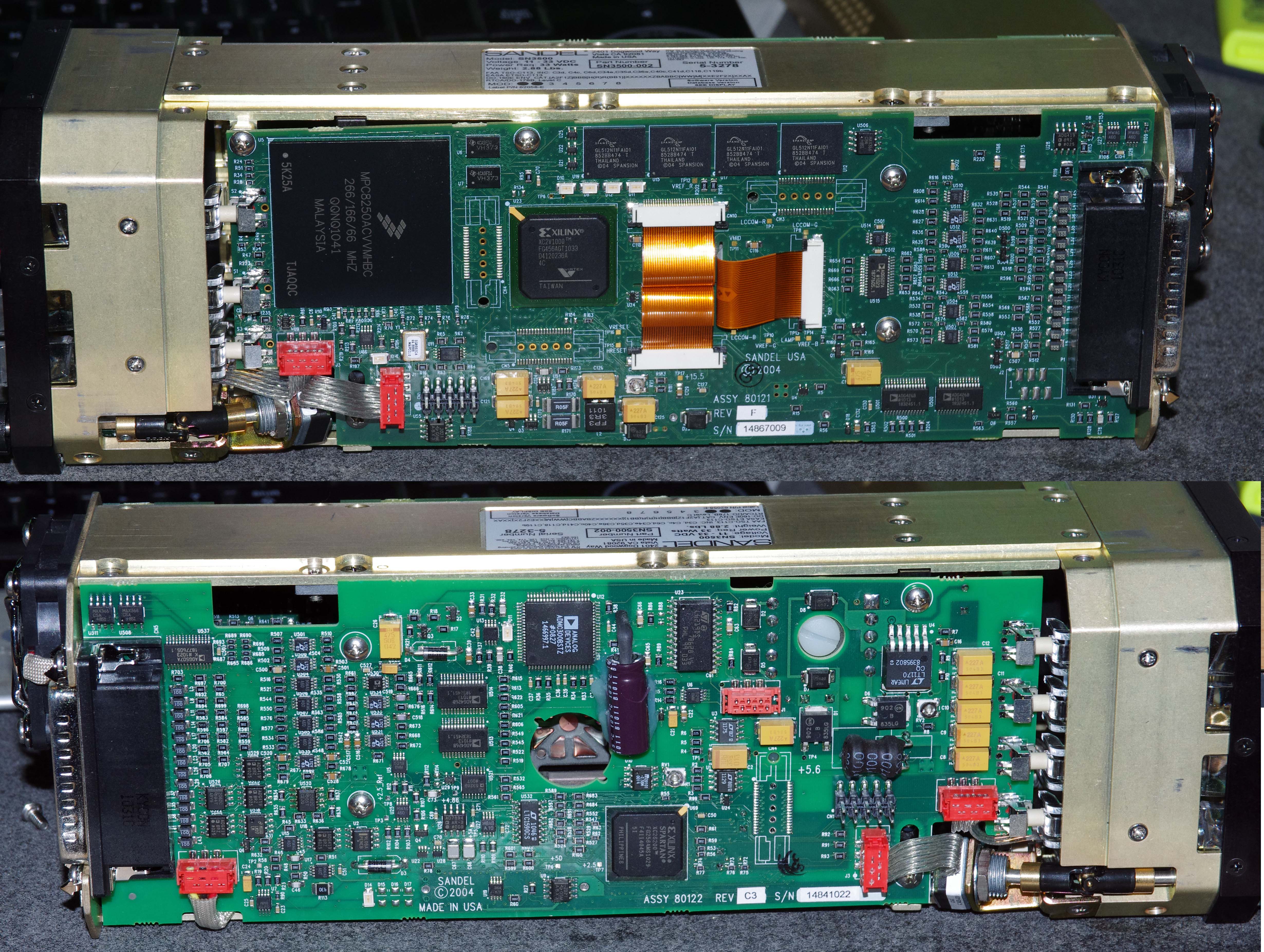
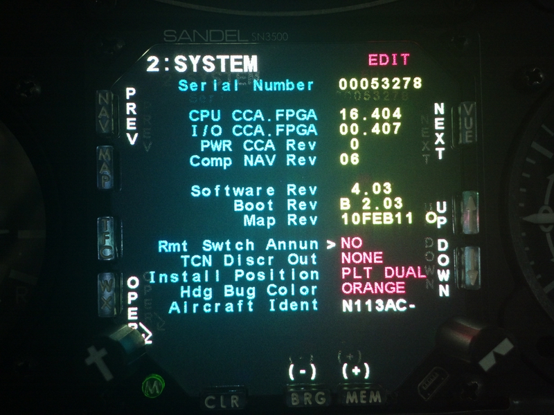
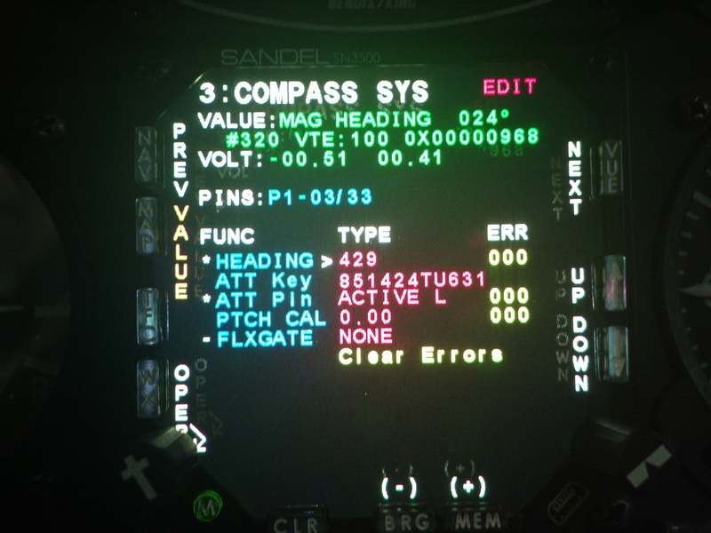
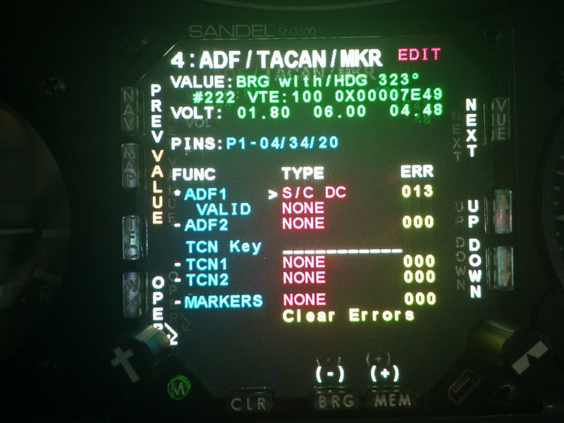
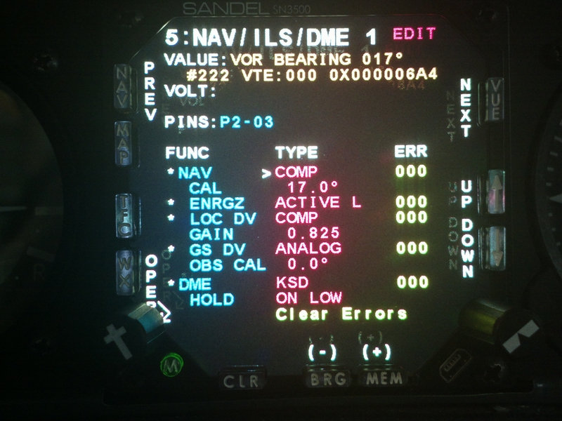
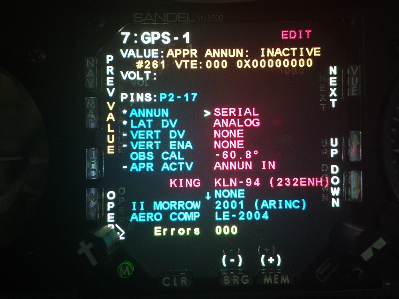
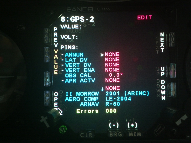
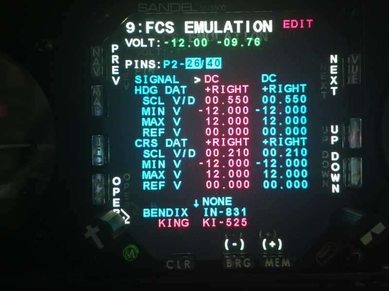
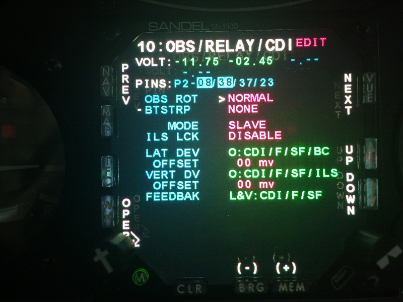
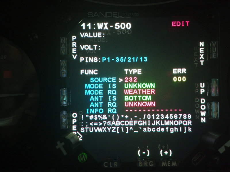
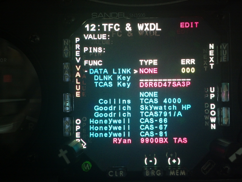
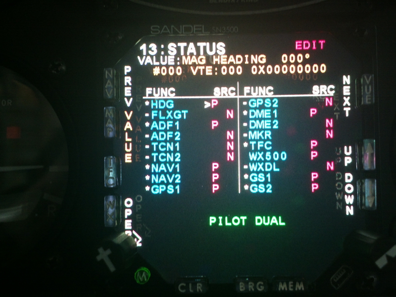
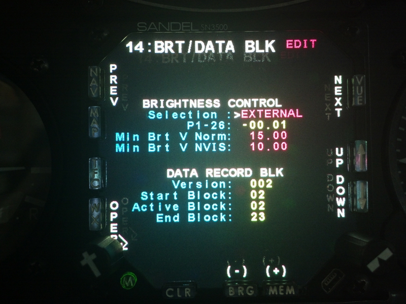
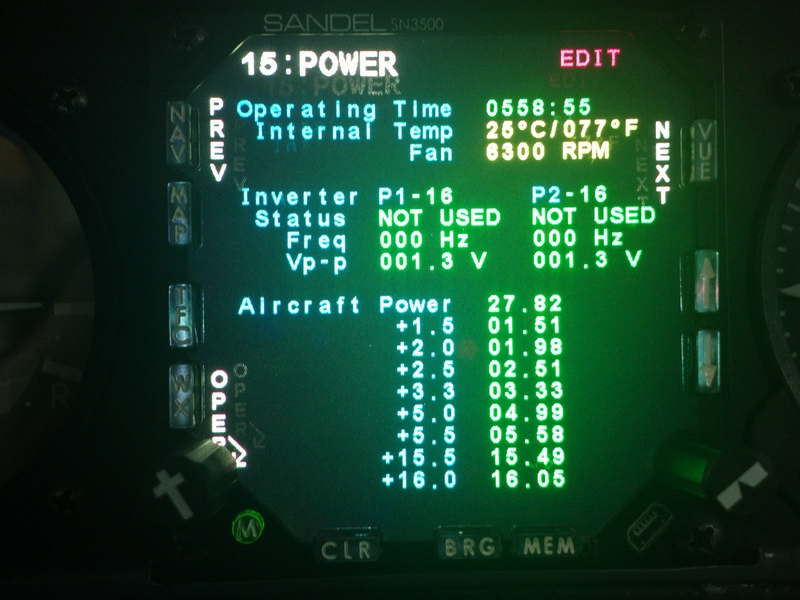
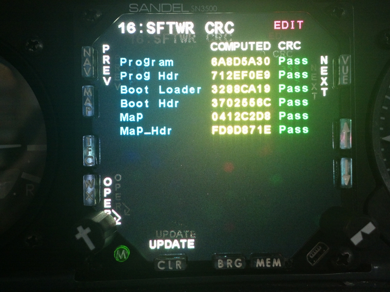
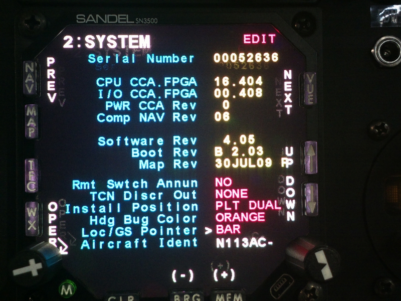
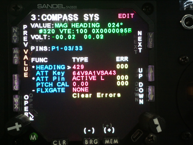
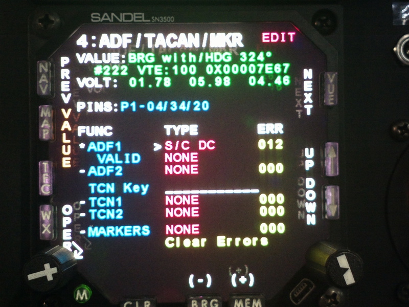
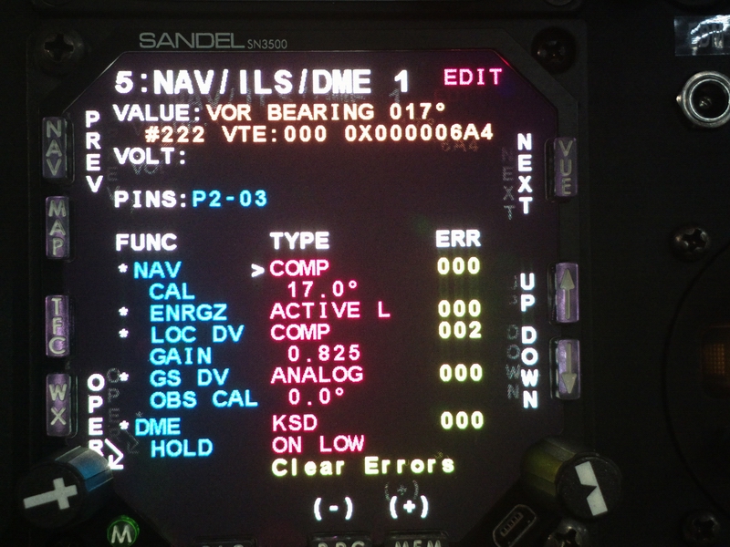
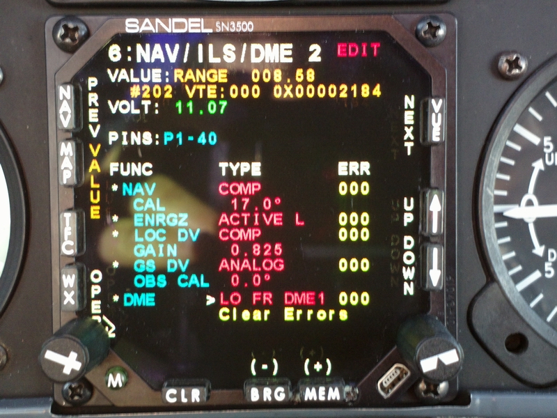
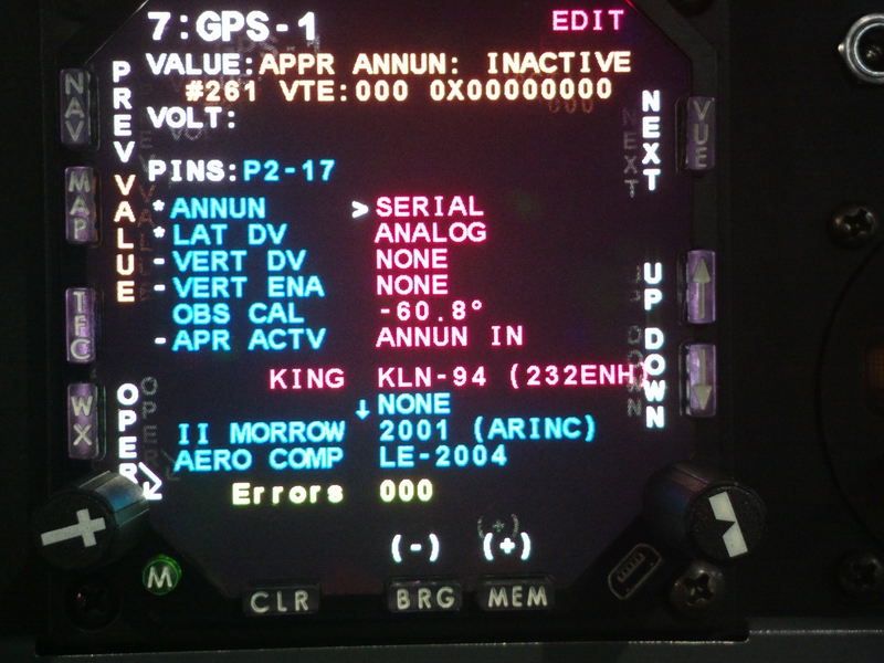
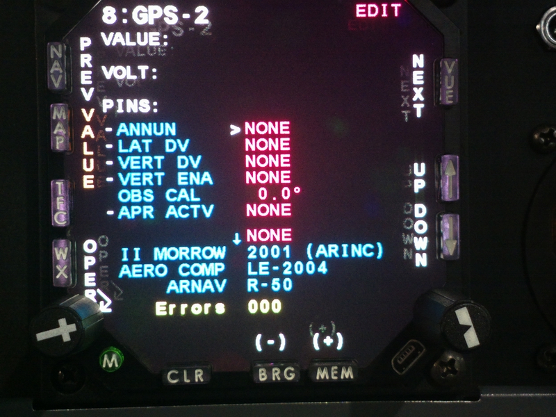
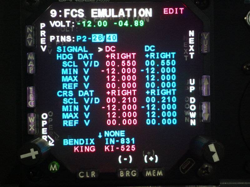
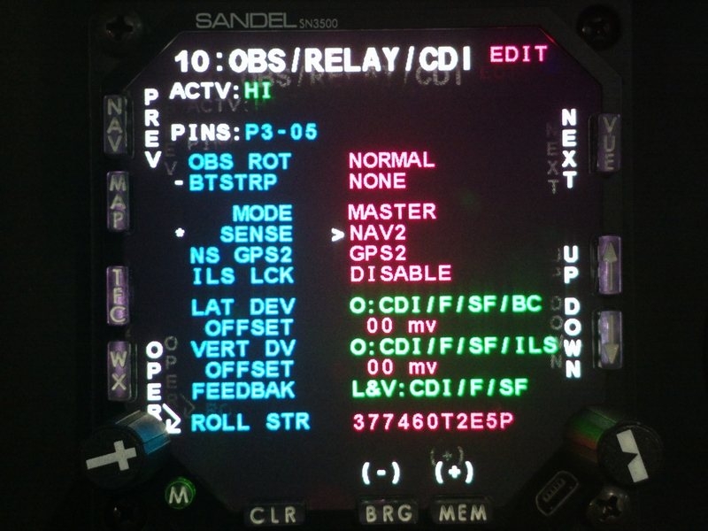
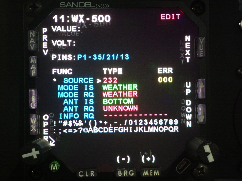
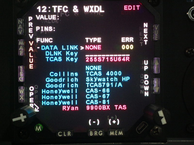
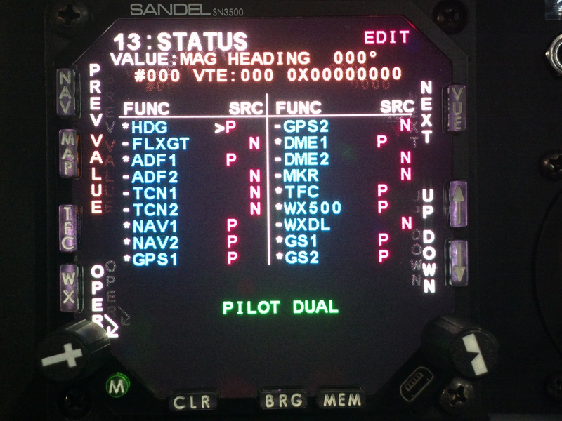
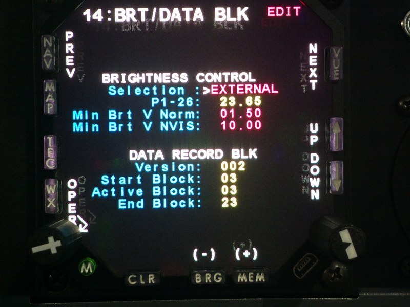
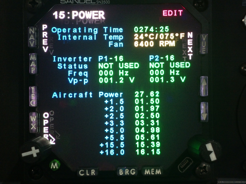
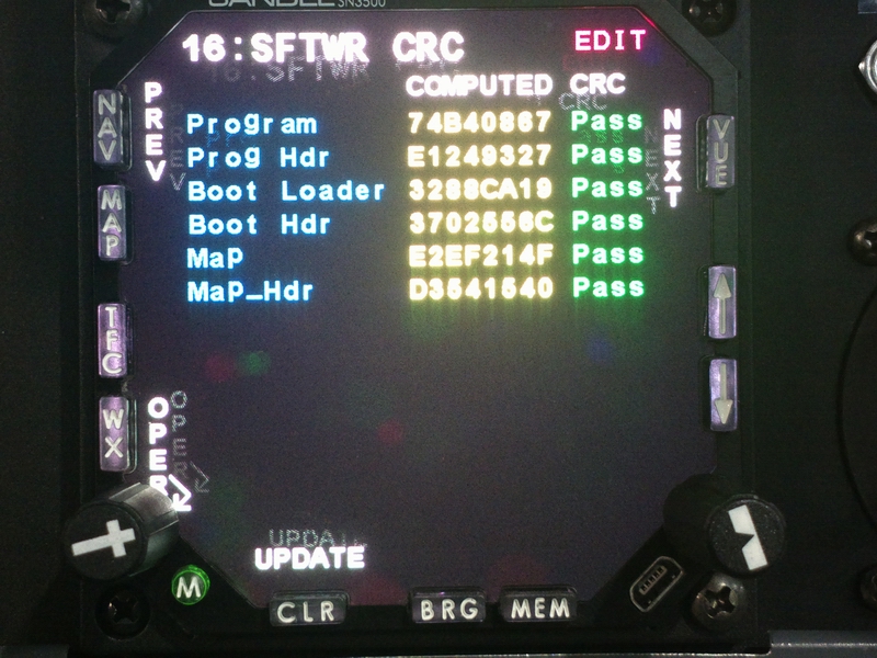