Honeywell KFC225 Autopilot Failures
When compared with traditional GA autopilots, the KFC225 works very well when it comes to stable and accurate aircraft controls in all phases of flight and under varying aircraft loadings. It is almost totally digital internally and avoids the traditional GA autopilot issues of control instability caused by the failure of cheap trimmer potentiometers and the drying-up of electrolytic capacitors used in feedback control loops.
However, during its brief life as an OEM-installed item (it never found a retrofit market, due to a very high price) it has proved to be a thoroughly unreliable product overall, mostly due to a number of serious design defects in the servos.
This article was originally written in 2004 to document a number of failures of this autopilot, installed in my Socata TB20GT aircraft which I have owned since 2002 and which was one of the last TB20s manufactured. Most other KFC225 users, in all airframes (Socata, Beech, Cessna, Piper, Diamond, etc) which used this autopilot, have also reported multiple failures and I have been trying to collate these to see if there is a pattern.
Following some bench investigation of failed servos I have re-written this article in August 2012.
Honeywell are aware of this site and of the issues and have been since around 2005. They pretend the issue does not exist.
Diary of KFC225 Failures
Up to April 2004
In my TB20GT, the KFC225 failed a number of times in both pitch and roll. The roll failures have all been caused by the roll servo. The pitch failures have been caused by faults in the computer unit, or by the pitch servo.
The Socata TB20GT aircraft was purchased new in May 2002.
The first failure in 8/2002 drove the ailerons to max deflection. I made a huge fuss and the entire KFC225 system was supposedly replaced by the dealer (Air Touring Ltd - now defunct). This type of failure would invert the aircraft in seconds and would be pretty dangerous if it happened in IMC. This failure was the only one which I did not witness personally.
Then there were various failures where the AP randomly selected a +2000fpm or -2000fpm rate of climb. This figure was actually being loaded, during level cruise, into the VS register which appears when the VS button is pressed. No fault indication appeared on the AP computer display. The KFC225 computer was replaced after this but not as far as I know the servos.
Then there were failures where it failed to hold altitude; the appearance being as if there was a static problem, but both altimeters, the transponder and the GPS altitude all agreed. The aircraft remained in trim. Again, no fault condition was displayed. These were never fixed because they could not be reproduced, and they would tend to go away if the AP was disengaged and immediately re-engaged. The KFC225 uses the altitude data from an encoding altimeter for altitude capture, and uses an internal high-resolution barometer for altitude hold. A failure to hold altitude is thus usually a failure of the internal barometer. But the mechanism for the automatic 2000fpm VS selection is a mystery; most likely a firmware bug.
Then there were failures where the AP would disconnect, illuminating the P or R LEDs, these indicating servo failure. A re-engagement of the AP would return normal operation for say 10-20 seconds only before the fault would return. This was captured on video. The servo(s) were replaced at this point.
The recent two failures, both taking place within a few weeks, appear to both be in the roll servo, where the AP fails to control the aircraft in roll. Luckily this one was captured well on a video, and the mpeg file shows the most recent one. The roll servo was replaced after the first instance, and this article is being written after the 2nd instance so no repairs have been done yet.
Roll failure 12-04-2004 (mpeg video, 7MB)
Note that the flight director does work correctly, so it cannot be an autopilot input problem. This is a typical manifestation of a servo failure. However the really disturbing thing is that the KFC225 doesn't appear to realise that it is unable to achieve anything; there are no error indications on its display. Surely it must "know" that the roll servo isn't doing anything! Why doesn't the software detect the fact that the roll servo is being energised for a period of some seconds, or tens of seconds, yet the roll/heading error is steadily increasing?
Due to the beat between the KFC225 display multiplex and the camcorder's frame rate, the KFC225 display doesn't show up well in the video, but it does show the normal annunciations.
June 2004
The failure in the above video was caused by a faulty roll servo, whose internal power amplifier burnt out. Amazingly, in this case, the KFC225 still passes its normal power-up diagnostics, with a totally dud roll servo. It is also apparent that a previous identical failure had the same cause.
I did some investigations on the failed servo, detailed here.
There has been another failure since, in altitude hold. The KC225 autopilot computer has been replaced again and it appears that its internal altitude (barometric sensor) encoder was faulty.
Up to this point, Honeywell offered me an indefinite warranty on the KFC225 system, because of the previous failures.
There is a firmware bug in the KFC225. It is possible, through pressing buttons in a certain sequence, to place it into a mode where it shows ALT (without any qualifications e.g. ALT ARM) but in fact does not hold altitude but is probably in a VS mode with a VS value of zero. This bug seems to have been fixed in some later firmware upgrade because I had not seen it later - 2012.
September 2005
This video (10MB mpeg) shows another roll servo failure. This is like one I got in 2003, where the KFC225 passes it's power up tests despite the roll servo being dead. This time, the servo failure is detected during flight but not on the power-up ground test.
In 2004 I saw an email from Honeywell to one of their dealers confirming this defect in the power-up test is correct design behaviour! This is appalling, especially as the Honeywell KFC225 brochure states
Superb Safety Features
Honeywell’s avionics engineers built impressive safety features into the
KFC 225. For example, the new KS 27XC servos used for pitch, roll and pitch
trim commands are carefully monitored and automatically disconnected when excessive
pitch and roll rates or excessive acceleration forces are sensed. Well-placed
voice messages and audible warnings keep pilots alert to the environment around
them. When the system is powered up, an extensive pre-flight test automatically
inspects the monitors and other components of the system to ensure proper operation.
Complete nonsense as far as checking the servos is concerned!
A later (2011 edited) version of the brochure is here.
A separate issue has surfaced in the KC225 computer over the past few weeks: one sets a VS of say -500fpm, when descending to a preset altitude. After some seconds, one notices that the VS reading on the VSI is not quite -500, and it is also obvious that the aircraft pitch is slightly up from what it was earlier. Entering the VS mode again reveals that the KC225 has modified the -500fpm figure to something like -300fpm. I have asked Honeywell what kind of external problem could cause the AP to self-modify the target VS but no meaningful response was received. Occassionally the AP modifies the preset VS value even within the 3-second window during which the VS figure appears, before it reverts to its normal display.
It is normal for the KC225 to randomly modify the preset VS by +/- 100fpm - clearly a firmware bug. Usually it modifies it downwards so e.g. setting 500fpm produces 400fpm and this is evident when VS is pressed again to show the actual figure in the unit. Normally this is not a problem in real flying, but it means the autopilot cannot be easily used to climb to the aircraft operating ceiling (20,000ft or so) because the climb rate there is only around +100fpm, and if you preset +100fpm, the KFC225 is likely to drop this by 100fpm, yielding 0fpm which is completely useless. So you preset +200fpm, which is OK if this gets modified to +100fpm, but is not OK if it gets left alone because one cannot climb at 20,000ft at +200fpm..... So, a better way to climb to these altitudes is to use the PIT (pitch hold) mode, instead of the VS mode, and adjust the pitch manually.
On this occassion, Honeywell contracted a UK avionics shop to examine the whole system. A number of items (in addition to the faulty roll servo) were supposedly replaced, though the avionics shop later denied that they replaced anything, but merely inspected the system.
November 2007
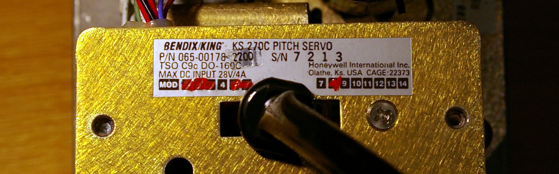
The autopilot has failed again, this time with a burning smell in the cockpit, accompanied by the SERVO circuit breaker popping. This time it was a faulty KS270C pitch servo.
Honeywell now washed their hands of their previous "indefinite" warranty, on the grounds that this servo had not previously failed. That was not actually true; the pitch servo failed in 2003 but as this was fixed under the original dealer warranty, I did not have a record of the details. What probably happened is that the servo replacement details did not filter back, via Socata's pipeline, to Honeywell's database. Soon afterwards, Honeywell washed their hands of any warranty, completely.
The servo burning out issue was claimed to have been solved with the following mod status, current at 26/11/2007
065-00178-2200 - KS270C - Pitch Servo - Mod 8 dated Feb 04
065-00179-0200 - KS271C - Roll Servo - Mod 9 dated Aug 04
065-00180-3500 - KS272C - Pitch Trim Servo - Mod 7 dated Aug 04
The servo in question was installed in November 2005 as part of a whole-system inspection following the 2005 failure and the label shows the expected mod status as #8.
However, on 4/12/2007 the above were found to be incorrect because the data on servo modifications is export controlled (believe it or not) and not everybody within Honeywell has access to export controlled documents. The current status is
065-00178-2200 - KS270C - Pitch Servo - Mod 9 dated Feb 06
065-00179-0200 - KS271C - Roll Servo - Mod 10 dated Feb 06
065-00180-3500 - KS272C - Pitch Trim Servo - Mod 7 dated Aug 04
The above mod versions were confirmed current 3/2010.
However, there is no indication that the above mods to anything useful.
In 2011 the roll servo acquired the dubious SB11 (Mod 11) which makes matters much worse (see notes below).
The burnt out pitch servo was opened and immediately the burnt out components were evident, as seen on previous burnt out servos
Component A (a large surface mount power resistor used for current sensing in the current limit circuit) got hot enough to crack open, unsolder itself and fall off, soldering itself to the next item below (another surface mount component to the left in the picture). Component B (an inductor) also became very hot and partly melted the plastic servo housing.
The complete PCB is coated with a hand applied conformal coating, to keep moisture off it.
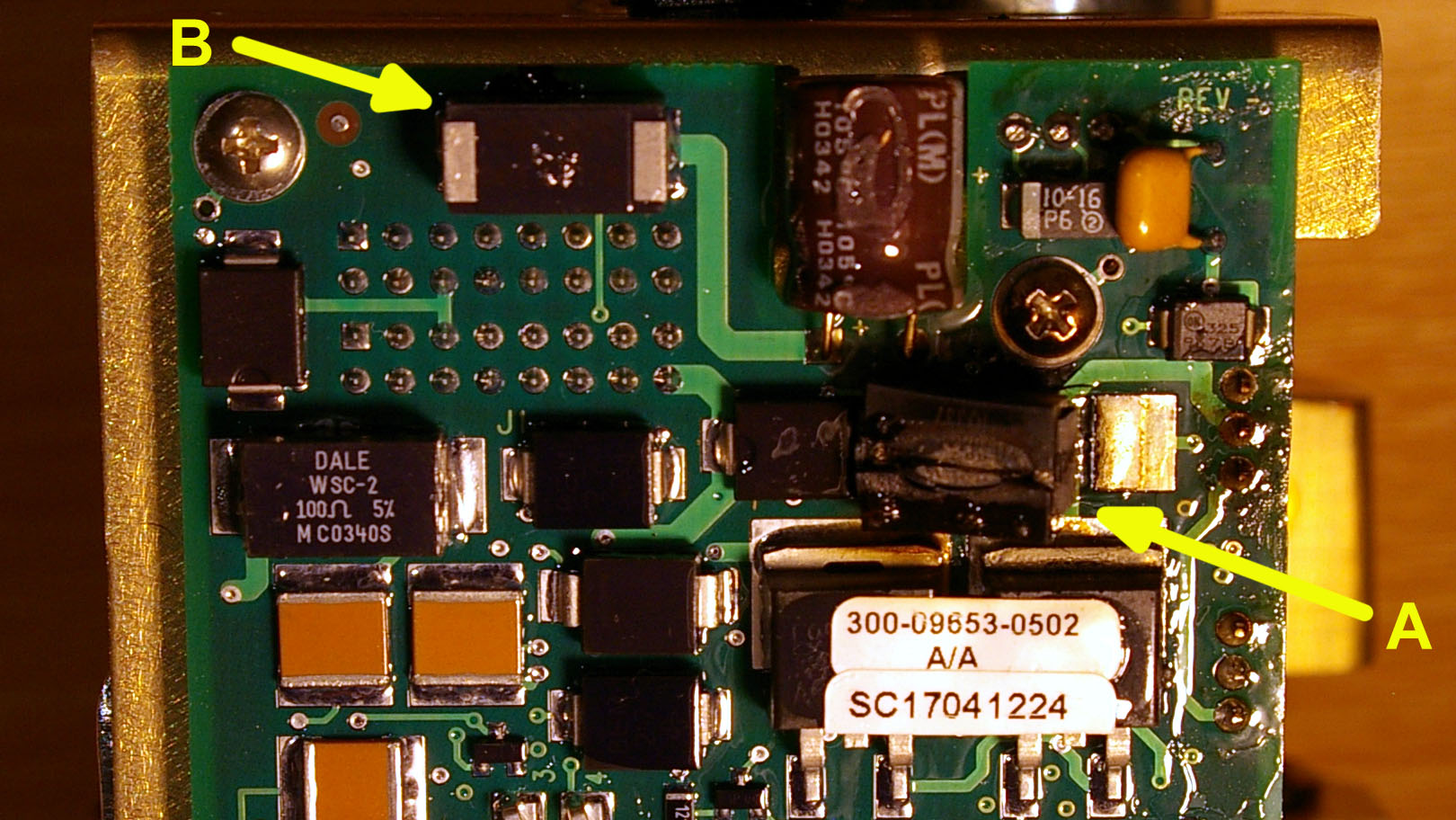
There was considerable amount of black soot (from brush wear) on the motor, with some more having been deposited on the strain gauge which measures the gearbox torque.
Note the attachment of a large weight on the motor/gearbox assembly. This assembly is free to rotate by a few degrees - this is necessary to enable the torque to be measured using the strain gauge, whose output is then used to drive the pitch trim servo. Evidently Honeywell had problems with stability and instead of solving it properly they fixed a weight to the moving assembly...
April 2008
The autopilot has failed again, again when airborne but thereafter consistently on the ground, this time with the computer reporting a pitch trim defect.
The simplest scenario for reproducing this is on the ground, with the engine not running (no vacuum) when the AP completes its 12 power-up tests successfully. If left in that state, all is fine. In this state, the electric trim (only) should function. However, as soon as the pitch trim (on the yoke) is operated, the trim itself works as it should but the autopilot locks itself into a continuously repeating "check pitch trim" message. This condition cannot be terminated other than by switching off power to the AP using the autopilot master switch.
An alternative scenario is with the engine running, when in principle one should be able to do additional tests because one has the signal from the vacuum driven horizon and the vacuum status signal to the AP is also OK. However, the autopilot fails pretty fast, with the trim running backwards at full speed by itself, and with the "check pitch trim" message, eventually transitioning into a continuous beep which again cannot be terminated other than with the power disconnect.
During an airborne test, the autopilot does the same thing but functions (despite emitting the constant warnings and beeps) in ROL, HDG, ALT modes with altitude capture working. The pitch trim does not work (never moves) and when it is eventually disconnected the pitch trim is well off. The following video shows the three situations:
Amusingly (or not) the KFC225 system passes all its power-up tests!
Superficially this looks like a pitch trim fault but the electric pitch trim works (for a while) which rules out a totally burnt out pitch trim servo. The KFC225 system uses a strain gauge subsystem in the pitch servo (schematic) to measure the pitch torque. The motor/gearbox assembly in the pitch servo has several degrees of freedom (in both directions) against a spring and the spring deflection is sensed by the strain gauges. The signal from the 4 strain gauges (which are arranged as a bridge, for temperature compensation) is amplified by two INA128 instrumentation amplifiers and the resulting two signals (voltages which are normally +3V and vary from +2V to +4V under operation) are fed to the KC225 computer which then generates a pitch trim signal to the pitch trim servo.
It was immediately found that the torque output from the pitch servo was duff. Both TRIM SENSE 1/2 outputs should be +3V when quiescent but one was at +3V and the other at +1V. Either the strain gauge(s) failed or one of the two INA-128 instrumentation amplifiers failed.
The servo was still under a 6 month warranty from the U.S. Honeywell dealer where it came from, and was returned for a swap. Honeywell's report confirmed my fault analysis.
September 2008 - with an amazing discovery!!
The autopilot has failed again, with the servo CB popping and a burning smell in the cockpit as previously. This time, on the ground, the 5A CB pops 2-3 seconds after the autopilot master is switched on. The fault is again in the pitch servo, KS270C, which was installed only 5 months ago
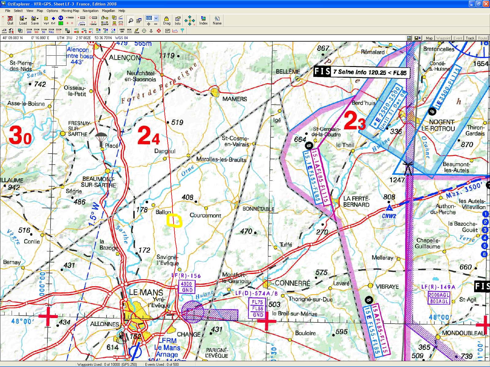
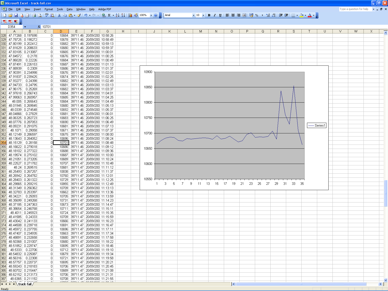
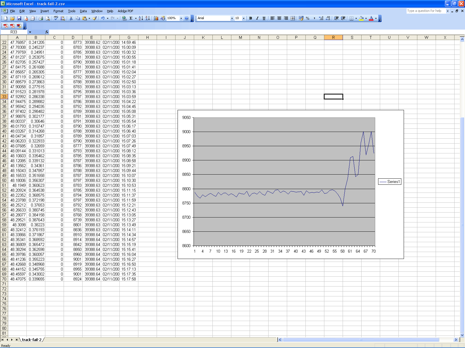
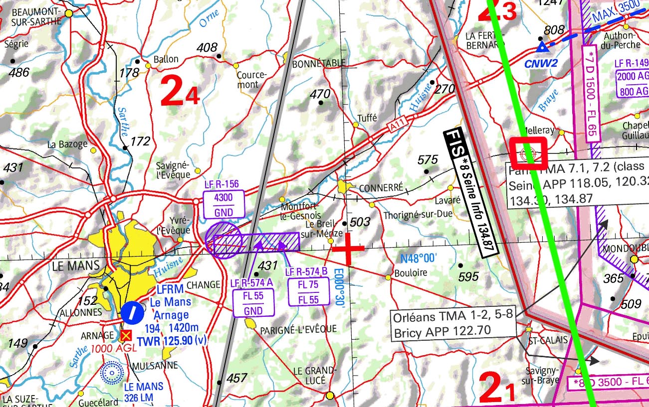
However, I had the GPS track for this flight and this failure led to an astonishing discovery: it happened in exactly the same place over France as the November 2007 failure for which I also happened to have kept the GPS track. The GPS track shows the altitude and one can easily tell when the autopilot failed because the altitude hold was lost and subsequent manual flight was not to the same standard.
The failure happened just north of Le Mans. This map shows the aircraft track in RED, and the location of the failure in YELLOW. The GPS data contains the following information recorded every 25 seconds:
Latitude degrees
Longitude degrees
GPS status
GPS altitude feet
Unknown field
Date DD/MM/YYYY
Time UTC
An example line is:
43.708445 -1.242245 0 10058 39711.37719 20/09/2008 09:03:09
The 2008 failure GPS data (whole flight LESO-EGKA) is here. The altitude plot from a section of it is here and it shows the loss of altitude control around the time=11:08:48 sample.
The 2007 failure GPS data (flight LEZG-EGKA; only data points around the failure are included) is here. The altitude plot from a section of it is here and is shows the loss of altitude control around the time=15:12:21 sample.
In both of the above failures, the GPS position, as closely as one can tell, is in the vicinity of
Lat 48.15129 degrees N
Long 0.28158 degrees E
Obviously this is not a coincidence and the only possible explanation is a ground based radiation source, coupled with an EMC (electromagnetic compatibility) deficiency in the autopilot equipment or installation.
Another autopilot failure happened in August 2003 and also occurred in this area, on a largely straight track EGKA-LFBT, at about 5000ft, but I no longer have the routing for that flight. This makes a total of three pitch servo failures around the same area in France. This is particularly significant since my only pitch servo burnout failures happened in this location. A 4th pitch servo failure was an internal one (described earlier above) which appears unrelated to external events.
I made some enquiries in France to see if there is some radar installation there but the French military apparently denied there is anything there. Nothing is marked on the aviation chart at the very spot, although one wonders what might be in the nearby LF(D) 574 A/B danger area. Possibly there is an anti-aircraft missile installation there, and the operators are routinely doing radar locks onto passing aircraft, to check how well the system works, or just for fun. The Google Earth location is around here.
A 4th failure in the same place in France happened in July 2012.
Update 2012: I've been informed that there is a SYDEREC installation there. This is a low frequency communications system operated by the French military.
February 2009
The KFC225 failed again, but this time it was different. I had used the autopilot normally for about 15 mins, then disconnected normally by pressing the red button. I noticed the two P R LEDs and the P/T symbol came on and stayed on - not the continuous beep though which had appeared on some previous failures.

The AP would not re-engage. I turned off the AP master switch, and after a few mins turned it back on. It passed the normal 12 power-up tests, but I noticed that while the AP was holding altitude and heading (the heading bug worked) it was not driving the pitch trim. For example, if holding altitude, as one varies the power, there should be re-trimming but there wasn't. This is a particularly nasty failure mode because you can end up with a badly mis-trimmed aircraft which could - upon AP disconnect - pitch up or down violently. However, manual pitch trim (the yoke switch, working through the KC225) worked OK so this wasn't a simple failure of the pitch trim servo.
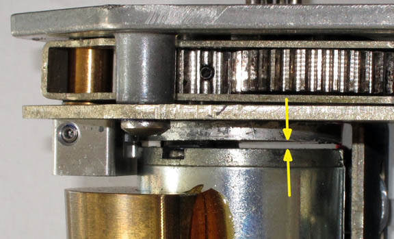
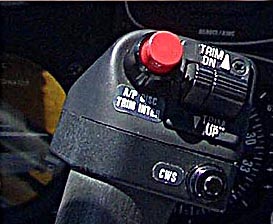
Subsequent tests found that, most of the time, the AP failed to do the power-up tests; at the end of test #2 (but before #3 appeared on the display) it illuminated the P R LEDs and the P/T annunciator symbol (within the display, as shown in the pic above) remained ON, and there was a continuous beep. Pressing the red disconnect button ended the beep but did nothing else. Very occassionally however, the power-up sequence did get completed successfully.
As I now have a complete set of spare servos and a couple of spare KC225 autopilot computers, it was quickly established that none of these was causing the problem! One can connect a replacement servo purely electrically - there is no need to mount it in the aircraft - because the AP cannot possibly tell if the servo is actually driving anything. So, it had to be something in the wiring or perhaps the sensors/switches.
It proved impossible to find an avionics shop able to look at it within a reasonable time frame.
I made up the RS232 cable for connecting a laptop to the KFC225 diagnostic port - a 1/4" jack socket normally located somewhere under the instrument panel. This uses a 4-pole "US NATO PLUG" picture which is easy enough to get from e.g. here. The diagnostic procedure is extremely simple: you use a VT100 dumb terminal - Hyperterminal at 9600,8,n,1 and XON/XOFF, on any laptop, as per instructions here. As soon as the autopilot is powered-up, it transmits a screen with a list of menu options on the laptop. I have the full installation and maintenance manuals for everything of course but cannot post them on an open website because some of them are very hard to get and somebody would eventually object...The diagnostic menu is very obvious and self-explanatory and it is easy to avoid messing around with important system parameters. However I would not recommend anybody doing this unless they really know what they are doing.
As the laptop has no physical RS232 ports, a USB-232 converter was used.
Using the diagnostic page wher the autopilot inputs can be examined, it took just minutes to check the various switches (trim up/down, CWS, etc) were fine.
The diagnostic error log showed Error 75 - "trim voltage too low". Input from one avionics old-timer suggested this is a well known one: a duff red-button disconnect switch. But this switch showed up fine in the diagnostics....
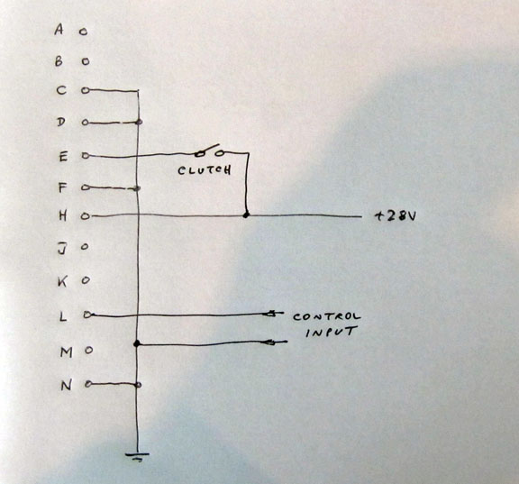
However it is seen in the schematic that the AP disconnect switch has two sets of contacts. One is used to tell the KC225 software that it is pressed. The other is used to interrupt the power to the servos - to "guarantee" that the clutches disconnect while the button is being held down. It is this second contact set which was not making a good contact. This switch is grossly under-rated for the job, because the load comprises of (among other stuff) three beefy servo clutch solenoids which are both inductive and capacitive loads so there will be significant arcing on the switch contacts. This switch failed after - very approximately - 1000 disconnects which is totally unacceptable.
By repeatedly waggling the switch, while watching the total aircraft current draw displayed on the ground power unit I was able make it work eventually - exactly as per the in-flight situation. With all three servo clutches engaged (by writing a "1" to them in the diagnostics) I could see the current changing by a couple of amps, and of course one could also hear the servo clutches operating.
These switches are horrendously overpriced but at least this time it was a simple enough cause. It would be nice to fit a better quality switch but the paperwork would be tricky...
April 2010
The autopilot has failed again. This time it was the KS270C pitch servo, yet again, but from the failure mode it was not a burn-out; it was like the April 2008 failure above i.e. the torque sensing output. It was nearly new but was out of warranty when it failed and its exchange value was derisory, so I bought a new (overhauled) one from the USA, as usual, and opened up the failed one. It took only minutes with a +28V supply to establish that the torque output (which is used to drive, via the KC225 computer, the pitch trim servo) was faulty. The two INA128 chips were fine; it was the strain gauge assembly which had something loose in it.
The strain gauge torque measuring feature has been notoriously unreliable in this servo model. Honeywell issued a mod (Mod 6, issued 3/2003, and implemented on all S/Ns above 5399) to "improve" it but a lot of Honeywell's mods are issued without an understanding of the fault, and sure enough this servo had this mod implemented... It is very hard to establish what the actual failure is; nothing is visible and I suspect that the design itself is defective in that the strain (the bending of the steel bar to which the gauges are glued) is too great for the gauges being used, and they simply crack...
There is no legal way to return this servo to service.
August 2010
The autopilot has failed again, with exactly the same fault as previously: the torque output.
Fortunately, this servo was still - just about - within warranty. This illustrates the need to always fly on avionics that are within warranty. In a typical warranty-replacement situation one installs a spare part (which was sitting on the shelf) and when the failed item goes back under the warranty the replacement will end up on the shelf where its warranty will expire. This means that if there is a failure, one ends up doing two replacements: one after the failure, and another to install the replacement unit when it arrives. I am sure the industry loves this, because it keeps the warranty claims way down.
April 2012
The autopilot has failed again, this time in a new way. There was pitch oscillation, with a period of approximately 2 seconds, in all phases of flight when on the autopilot. Initially it showed up only during turns but later it also did it noticeably enough in level flight.
It turned out to be the pitch servo (again). The unit removed was a latest-spec one sourced new from South East Aerospace in 2010, but it is obviously out of warranty now and thus worthless.
There was no obvious electronics explanation for this behaviour... It could be that some component failed and caused the servo gain to increase way out of spec. I did notice that the ground-test pitch movement speed (the rate at which the elevator is driven when the autopilot is turned on when on the ground) was a bit too high so maybe that's it. A big increase in the open loop gain of the pitch control loop would cause instability; this is a common problem with old analog autopilot that stupidly use electrolytic capacitors to determine the control loop time constants, and over many years these capacitors dry out and their capacitance reduces. But the KFC225 control loop is done digitally...
Opening up the servo... sure enough we see a broken wire on the tachometer which explains the fault precisely
It was negligent to solder those four wires to the motor and the tachometer without any form of strain relief (e.g. heatshrink sleeving). I have since seen the inside of several other pitch servos which also have no strain reliefs, so this is not a one-off.
I sent the above photo to the supplier of the servo... no response. There's a suprise.
However, that was not all that was wrong. The swivel of the motor+gearbox assembly
(required for the torque sensor mechanism to work) was restricted to only moving
one way. It turned out this was due to the gearbox being incorrectly assembled,
with the bottom plate screws (which basically hold the gearbox together) loose
as shown in this video (1MB MP4). Eventually this would
have fallen off and possibly jammed the gearbox, forcing the pilot to rely on
the external slipping clutch to be able to control the aircraft sufficiently
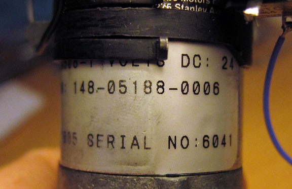
to land it. If Honeywell are interested in finding the idiot who did that, they
can find the serial number here ![]() The servo was S/N 10632 Mod 9. I have seen several servos with the same serious
defect, so this is not a one-off.
The servo was S/N 10632 Mod 9. I have seen several servos with the same serious
defect, so this is not a one-off.
The KS270C servo is now (2011) $2900 new outright, or $2150 new exchange. This is a very poor deal for a servo which has only done about 150 flight hours over 1.5 years.
Unfortunately this turns out to be a common defect. Here is another example of a servo seen in 2012, S/N 4872, with the same issue caused by chimp-grade workmanship and quality control at Honeywell
Of the three screws holding that end plate onto the gearbox, one was missing. It had not fallen out, because after these become unscrewed by about 2mm, there is nowhere for them to go after that, due to lack of room. And the other two screws were totally loose. Unfortunately, the servos with the end plate loose cannot be easily repaired because there is no obvious way to get access to the three screws without a complicated dismantle of press-fit components. One could perhaps salvage the servo by degreasing the mating surfaces (by squirting IPA into the gap) and gluing them together with epoxy, obviously taking care to not get any epoxy near the gearbox output shaft and then re-lubricating any bearings, gears, etc.
July 2012
The pitch servo has failed again. The autopilot continues to work but there is no altitude hold. The torque sensor works OK in that pushing/pulling the yoke activates the pitch trim. Startup checks pass OK; not that that means a lot with these servos... It happened on a long trip comprising of two 4hr+ flights, and it failed near the end of the second flight, at FL140, over N. France.
Astonishingly this is the 4th failure at the same spot in France. The altitude data is here and the map showing the spot where it happened is here. Obviously the French have something down there which is zapping the aircraft with intense RF and is destroying the servos.
Unfortunately this servo is out of warranty... It did not "burn out" as such. The autopilot still passes the power-up checks and fully runs - but there is no pitch (elevator) actuation.
A post-mortem on the servo found a destroyed motor (which ran if "assisted" by hand but had a dead spot in a particular angular orientation of the commutator) and a defective tachometer whose brushes were worn enough for it to produce a very rough waveform. In this relatively rare case, the motor went open-circuit before the amplifier burnt out.
September 2012
The pitch servo has failed again, on a flight in SE France. The scenario is identical to the July 2012 one above.
This time, the servo produced a lot of burning smell, which filled the cockpit, as in the Nov 2007 failure. No circuit breakers popped.
Opening up the servo (which, of course, is out of warranty) reveals that the 0.3 ohm current sensing resistor became very hot and partly melted the plastic servo housing. More interestingly, the motor is totally dead - almost a short circuit.
At this point I had enough and spent considerable time examining the design... and discovered it is even worse than I thought previously.
September 2016
On a 7hr flight around FL160, the system started to porpoise in pitch. It wasn't enough to show a change of altitude or vertical speed but it was very noticeable to the pilot.
Mysteriously, on a return flight, the problem was gone.
Porpoising (or roll oscillation, if it is the roll axis) nearly always is the result of an excessive loop gain i.e. the servo running too fast.
An examination of the pitch servo revealed a defective tachometer, outputting a below-normal voltage. In fact the voltage was a rough sinewave with an all-positive value, whose average value was about 1/3 of normal, which caused the servo to run about 3x faster than normal. The tacho was cut open but nothing obvious was seen, apart from a worn commutator.
However, the motor was found to be full of black soot, and both of the ball bearings (one at each end of the armature) were almost seized due to ingress of dirt. They are partially sealed but the stuff still got in.
Failure Analysis
With absolutely zero support from Honeywell after the first couple of years, I have become one of thousands of KFC225 owners who are stuck with it. A few have been paying up their extended warranties, but they still have to fly back to a Honeywell dealer to have the servos changed...
With the help of various people who shall remain nameless ![]() I managed to get the full maintenance manuals on the complete KFC225 system
(the KI256 horizon, the KC225 computer, and the 3 servos) and together with
a pile of pilot-donated defective servos I started to analyse what might be
causing the problem.
I managed to get the full maintenance manuals on the complete KFC225 system
(the KI256 horizon, the KC225 computer, and the 3 servos) and together with
a pile of pilot-donated defective servos I started to analyse what might be
causing the problem.
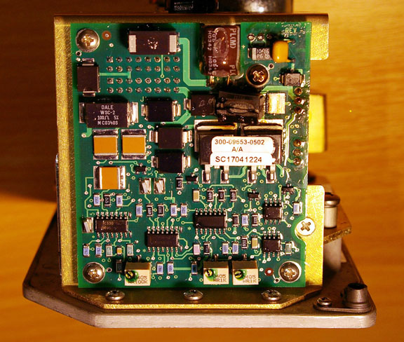
The KC225 Computer
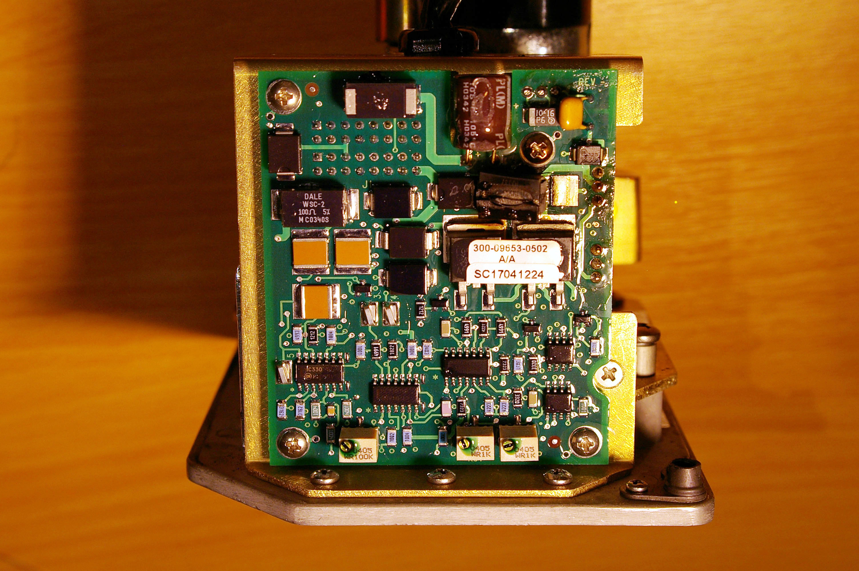
The KC225 computer appears to be designed reasonably "thoroughly", which is just as well since it is a very complex piece of equipment on which no bench troubleshooting is practical. It has plenty of protection components on inputs and outputs. The tendency to use bizzare component values all over the place (e.g. 4.64k instead of 4.7k, where anything from 1k to 22k would do) suggests that the designer was an "fresh ex university" type rather than a seasoned hardware designer, and shows a complete detachment between design practices and manufacturing costs, but there is no real harm in it. The resulting hugely inflated component stock costs money of course but also increases manufacturing costs, via the need for multiple feeder reel swaps on the SMT pick-place machine. There is a general excessive use of discrete components which results in the KC225 computer being totally packed with densely populated PCBs, which makes troubleshooting impossible without special fixtures. The large component count decreases reliability directly, and through the need for multiple PCB interconnections.
Unfortunately the computer does have one constant problem: a serious software bug which causes the voltage going to the servos to contain a constant jitter on it, which causes the servo motors to run, forwards and backwards, through a part of a revolution. The motion does not get through to the aircraft control surfaces because it is taken up by the backlash in the servo gears, but it obviously does reduce the motor (and tachometer) life.
The following videos show the waveform going into the servo from the KC225 computer, in a stationary aircraft, with the autopilot engaged in the AP + HDG mode, and the resulting motor movement:
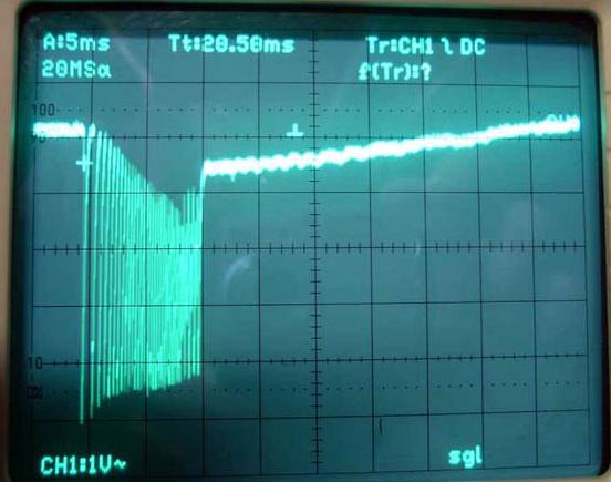
A screenshot from a digital scope is below
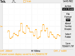
To put this in context, the above waveform is about 200mV peak which is about 2% of the full-scale servo input range. It causes the motor to run at approximately 20 RPM, for a fraction of a second, which is more or less what the video is showing.
The smallest Y-axis quantum, about 30mV, corresponds fairly well to 1 LSB of an 8-bit D-A converter (with a ~10V FS) but the KFC225 doesn't use a D-A converter (DAC) for the servo outputs; it uses software pulse width modulation and lowpass filtering to emulate a DAC. So the sharp steps are probably the result of some crude computation done with 8-bit integers. Maybe Honeywell implemented the whole control loop using 8-bit integers? If working with 7 or 8 bits, one needs to lose only a few bits (due to e.g. integer underflow) and the result will be an extremely rough waveform going to the servos.
Autopilot installers familiar with the KFC225 system have long commented that the KC225 computer is "constantly driving" the servos, resulting in their poor life. The above is the final proof.
It's important to realise that the above constant motor activity is present regardless of whether the servo clutch is engaged. So even if you fly with the autopilot OFF (but powered up) the motor and the tachometer are being worn out.
Honeywell need to fix the KC225 software...
The Servos
The servos are of an inept design, with no attention paid to the most basic
things like input filtering, frequency compensation for output stage stability,
output stage slew rate limiting for motor protection, etc. The motor is of poor
quality. The tachometer is a stupid idea which is as guaranteed to fail as a
vacuum pump and could easily have been avoided with e.g. a shaft encoder. The
"designer" did however calculate the component values to high degrees
of precision so there are resistors like 4.22k, 9.09k, etc ![]() There is nothing technically wrong with using such component values but it shows
the designer had a poor knowledge of electronics. The poor design is compounded
by poor build quality and poor QA; examples include wiring with no strain relief
and loose screws which could become a real flight safety hazard.
There is nothing technically wrong with using such component values but it shows
the designer had a poor knowledge of electronics. The poor design is compounded
by poor build quality and poor QA; examples include wiring with no strain relief
and loose screws which could become a real flight safety hazard.
The basic mechanical design (the external gears, the clutch, etc) of the servos appears to be good. The motor-tachometer gears wear out eventually but this is very rarely a servo failure primary cause.
Referring to the KS271C servo maintenance manual; the latest October 2005 version, I sent this analysis to a number of engineering contacts at Honeywell in 2005. Acknowledgement was received but no further comment at the time and they did acknowledge another report sent in 2008, again without comment. In July 2012, this article was sent to Honeywell's chief executive, Kevin Gould, who did not reply.
I have asked Honeywell reps at exhibitions etc over the years and their replies range from an outright denial of any issue (which they have also given to a number of aircraft owners) to assertions that the issue is specific to only the one aircraft type (the TB20).
The above analysis still mostly holds but I have since discovered there is an error in it: the servo amplifier (this is a typical one, used in all three servos) is a purely linear, not switch-mode, design. It is easy to make that mistake on a quick look at the schematic because of the way it is laid out. The two upper MOSFETs are switched hard-on one at a time (just like in a switch-mode bridge design) but the two lower MOSFETs are controlled linearly. The two upper MOSFETs "should" therefore have a very low power dissipation and are PCB (SMT) mounted, while the two lower ones are mounted on a piece of the servo metalwork.
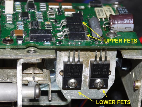
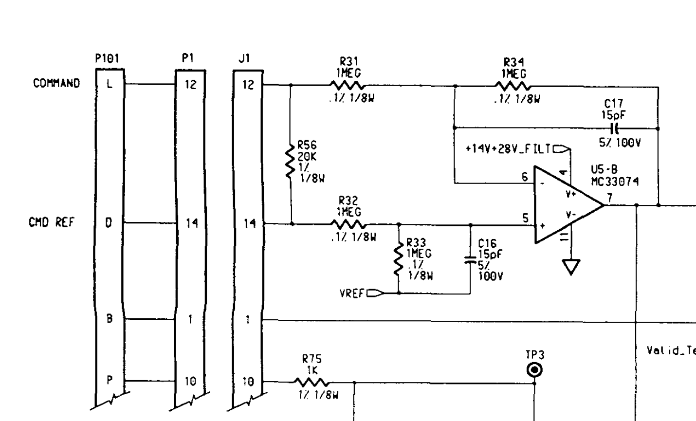
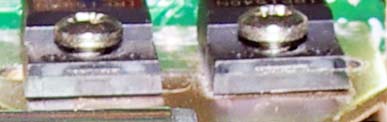
There are several areas of weakness in the design. The servo amplifier is on a small PCB (this pic is from the KS270C pitch servo, with R11 melted)
1. The amplifier input has no effective RF protection
Why RF protection? Any input signal beyond the bandwidth of the servo (basically anything over a few Hz) will thrash the motor all over the place and will drive the servo into current limit. That, in turn, will eventually destroy the servo through overheating (see notes below).
The input schematic is here and it can be seen there is no passive (broadband-effective) filtering. R32 and C16 do form a reasonable passive filter on the CMD REF input. However the COMMAND input filter is R34 and C17 which is an active filter using the U5-B op-amp and any active filter will work only within the bandwidth of the op-amp itself; in this case it will be useless above about 1MHz. This arrangement is particularly useless since CMD REF is driven from a virtual ground - the actual control input is COMMAND. Passive filtering should have been incorporated on both inputs. Any RF signals entering the servo cable will reach the servo amplifier and cause it to behave unpredictably.
It is obvious that Honeywell are aware of the RF issues because they have peppered the servo with ferrite beads. There are beads on the motor wires, on the tachometer wires, and there are tiny beads (too small to stop anything below GHz frequencies) on the Positronic cable connector.
It looks like somebody decided to throw in everything "ferrite" from
the Digikey catalogue ![]() but in fact all the beads are way too small to do anything useful.
but in fact all the beads are way too small to do anything useful.
Looking at the failures I have had over the same spot in France, it's obvious that RF interference plays a major part in the KFC225 servo failures. Interference from other aircraft systems is also likely to play a part: one TB21 I know of is getting roll servo failures every few tens of hours and he has an Avidyne 600 TAS and a Honeywell KRA10A radar altimeter, which may or may not be a coincidence...
What one cannot tell, without extensive flight testing with a servo with various wires coming out of it, is whether the interference is affecting the servo directly (by entering its input) or whether it is affecting the KC225 computer or its inputs and causing it to generate a signal to the servo which drives it into current limit and destroys it via that route.
I am very sure that it is the latter, and quite possibly some RF event causes the KC225 software to throw away a lot of precision in its control algorithm which results in a massive growth in the size of the LSB, and since the output voltage will always "oscillate" around 1 LSB, this will drive the servo into current limit...
The only thing which might protect the servo in the latter scenario would be a reduction in the current limit value, to a level which the motor can safely withstand for a reasonable time, and changing the MOSFETs and their heatsinking arrangement - see below.
My bench tests show that a 1V peak amplitude signal at 10Hz will drive the servo into a virtually continuous current limit, which will burn it out, while the amount of output gear movement will be too small to be evident in aircraft behaviour.
2. The Current Limit Circuit is ineffective
This is formed by R11, Q1 and Q2, and is activated at around 2A. It has several major design defects:
(a) There is no frequency compensation so severe oscillation takes place when current limit is reached (with high frequency components reaching into the UHF range and thus liable to interfere with aircraft systems), and Mod 11 makes this much worse;
(b) The current limit value of 2A is way too high given that the stall current (at 28V) of the motor is around 1A, so the amplifier will happily melt the motor without even going into current limit, but then it melts itself due to (c) below
(c) The IRFI540 MOSFETs are too small for the potential power dissipation in the 2A current limit condition, and have insufficient heatsinking.
The motor current during normal operation is generally below 0.2A, and the chassis-mounted lower MOSFETs (which in normal operation do all the heat dissipation) get barely warm.
They get a lot warmer in current limit (2A) conditions though, and 56W (28V and 2A) in a single IRFI540 MOSFET exceeds its absolute maximum (and with an infinite heatsink!) rating of 48W. The high thermal resistance junction-to-case (J-C) being 3C/W (typical of these convenient fully-overmoulded TO-220 packages) would cause the +175C maximum junction temperature to be rapidly reached even on an infinite heatsink, and with the real heatsink being of the order of several degC/W we are looking at a junction temperature way above +175C so it is not suprising these MOSFETs melt readily.
What tends to happen is that one of the lower (chassis mounted) MOSFETs melts first and goes short-circuit. Then one of the upper (PCB mounted) MOSFETs melts and goes short-circuit. Then R11 gets extremely hot. Sometimes, the circuit breaker trips and stops the melting process, but in most cases R11, and sometimes the PCB mounted FET, unsolders itself from the PCB and either falls right off or comes off far enough to interrupt the current. The strong burning smell appears to be usually from the motor armature winding going up in smoke as it is dissipating about 56W (28V, 2A), but R11 makes a contribution here too...
Using these plastic-cased MOSFETs is "elegant" because it avoids thermally conductive washers (itself a wise move if you have these assembling the servos) but there is a heavy price to pay in the junction-to-heatsink thermal resistance which means they melt after just a few seconds in the current limit condition.
Sometime around 2005, Honeywell modified the KS271C roll servo with another inept and ineffective modification, which uses a thermistor (see RT1 on page 2 here) to sense the servo temperature and reduce the current limit threshold at higher temperatures. However, I have not seen any servos actually fitted with this. The latest roll servo I have seen (burnt out) is around S/N 12500 and that did not use that mod.
In late 2011, Honeywell issued SB11. This
seems to be an idiot-motivated attempt to deal with the servo burning out issue.
It simply shorts-out the current sensing resistor and removes the other current
limit components. Unfortunately, the removal of the 0.33 ohm resistor R11 increases
the already poorly defined voltage gain of the MOSFET output stage, causing
it to oscillate continuously at high frequencies and causes the servo to emit
massive RF interference which (in the TB20GT aircraft) can be heard in the headset
![]() This scope trace
shows the RF coupled into the aircraft supply:
This scope trace
shows the RF coupled into the aircraft supply:
Also, one is now relying entirely on the KFC225 autopilot servo circuit breaker
to trip, as the only means of protection from an electrical fire ![]() Despite these obvious warning signs, Honeywell did not withdraw SB11 and in
October 2012 it was issued by airframe manufacturers, including Socata!
Despite these obvious warning signs, Honeywell did not withdraw SB11 and in
October 2012 it was issued by airframe manufacturers, including Socata!
3. Marginal Stability
The open-loop voltage gain of the MOSFET output stage (Q10 or Q11, whichever one is conducting at the time) is poorly defined and the servo is often right on the verge of going unstable; whether it does so will depend mostly on the batch of MOSFETs used.
While there is feedback from the output back to U1B and U1C, there is no frequency compensation around the output MOSFETs, which are fast devices and thus liable to oscillate at high frequencies. This will rapidly trash the commutator, via heavy arcing.
The design should have included frequency compensation from the output (drain) of Q10/Q11 (whichever one is conducting at the time) back to its gate. That should be adequate for both normal operation, and the current limit condition.
There is no evidence that Honeywell ever used an oscilloscope ![]() when developing these servos.
when developing these servos.
4. Motor Issues
The motor has ball bearings but is otherwise of poor quality, with particularly cheap and nasty commutator construction. Yet, it still should not be failing as often as it does...
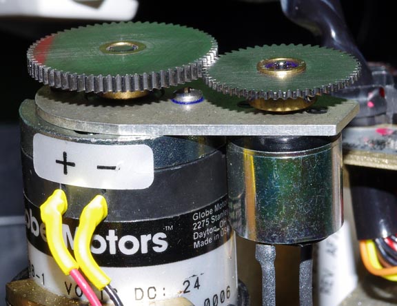
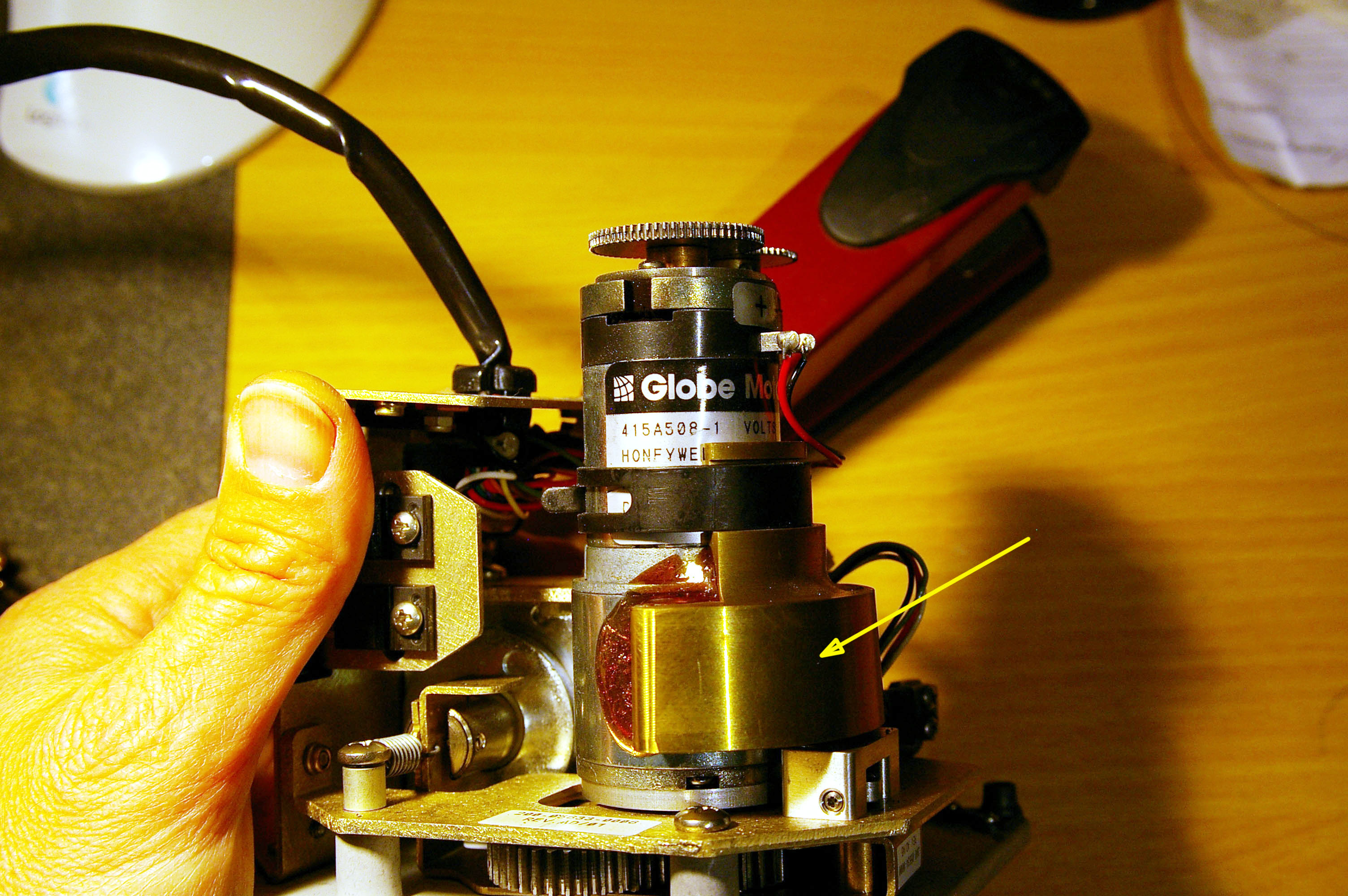
This is a US-made Globe motor, custom made for Honeywell, with custom windings, custom shafts at both ends, etc. Globe won't discuss any Honeywell part numbers other than to say the motor has "custom windings". However, from the Globe website it is obvious that the Honeywell motor (Honeywell P/N 415A... e.g. in the pitch servo it is 415A508-1) is a custom version of the IM-13 (data sheet copy).
Testing a number of the Honeywell motors, I found that the majority were damaged,
to varying degrees, with some totally burnt out (armature wire melted and sometimes
open-circuit and sometimes partly shorted) and extremely smelly. The motor condition
can be checked on a test with a variable voltage power supply (disconnect one
of the motor wires if you are testing the motor in situ ![]() ) but is also readily apparent when testing the whole (otherwise apparently
working) servo with a low-amplitude sinewave control waveform of about 1V peak,
0.1Hz. It can also be checked by putting an oscilloscope onto the motor terminals
and turning its shaft by hand; a trashed motor generates a particularly horrible
waveform which has long gaps in it.
) but is also readily apparent when testing the whole (otherwise apparently
working) servo with a low-amplitude sinewave control waveform of about 1V peak,
0.1Hz. It can also be checked by putting an oscilloscope onto the motor terminals
and turning its shaft by hand; a trashed motor generates a particularly horrible
waveform which has long gaps in it.
The obvious explanation for the burnt out motors is that the servo amplifier tried to drive the motor with a current which the motor cannot carry and which heats up and melts the windings. In straight operation this is impossible because as an increasing voltage is presented to a DC motor, it draws more current, speeds up and the back-EMF reduces the current, to a value appropriate for the new speed. The Honeywell motors draw of the order of 0.5A at 28V and they can do this continuously. (Actually the pitch servo motor draws about 0.5A and the roll servo motor draws about 0.3A; their armature resistances are inexplicably different at 16 and 30 ohms respectively). The only way to get more current into the motor is to drive it with a waveform which it mechanically cannot follow i.e. backwards and forwards, rapidly.
The likely explanation for the less common burnt-out commutators is a high frequency version of the above, which the motor cannot follow and which causes excessive arcing on the commutator.
5. The Tachometer
To achieve a defined and stable open loop gain (necessary for stable control of the aircraft) a gear-coupled DC tachometer is used
which ensures that the servo runs at a specific RPM for a specific control voltage. If the tachometer is disconnected, the servo runs approximately 2x faster and the aircraft becomes unstable on that axis.
The tacho would have been a reasonable solution 50 years ago but today it is a stupid idea because it is certain to wear out fairly quickly. A shaft encoder or a Hall sensor should have been used instead. When the tacho wears too far, it generates a very rough waveform, sometimes with gaps in it, which causes the amplifier to drive the motor with the opposite waveform and this quickly destroys the motor.
These tachometers, even when new, produce a fairly rough DC voltage, with 5-10 % of ripple and "muck", and are easily checked with an oscilloscope. A tacho with a trashed commutator will produce a voltage which has a very visible "high frequency" component, on top of the usual waveform which is superimposed onto the DC output and is visible in the following pic which also shows the said high frequency components

This pic shows a worn-out tacho commutator
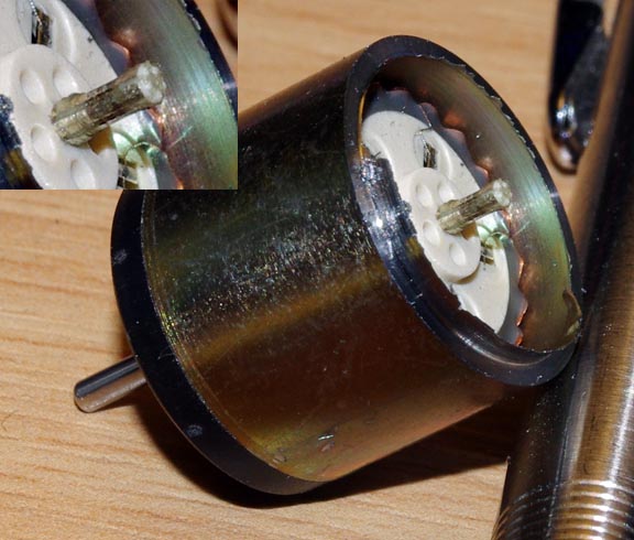
The tachometer uses metal brushes which have a much shorter life than carbon brushes, but are probably the least-bad solution for an application where the brush current is insignificant and carbon brushes would get glazed. Unfortunately the metal brushes need to wear only a tiny amount for them to become useless. I have seen several tachometers which produced a rubbish waveform but whose commutator looked fine...
The tachometer related circuitry shows another piece of inept design. The output waveform from the tacho is rather rough, yet they use its signal directly with little smoothing, via U5-A, feeding it into the error amplifier (U1-C) so the motor is driven with the tachometer's output ripple! It's amazing the whole thing works at all. The coarse tacho waveform will be partly responsible for the poor motor life.
6. The Clutch Solenoid
This works fine but draws about 0.5A and thus dissipates about 14W. This is a huge amount of heat to get rid of. It is normally OK, especially as the servo is mounted on the substantial piece of aluminium in the aircraft, but obviously will reduce operating margins when flying in high ambient temperatures.
7. Poor Quality Control
Various examples of this are documented elsewhere in this article, but one of the most shocking ones was found in 2012, on a KS271C roll servo, which I bought several years previously, to carry as a spare. It came from South East Aerospace and came with Honeywell's overhaul documentation, dated 2004. S/N was U3397. With the 6-month warranty long expired anyway, I decided to open it up to make sure the insides looked OK, with no loose screws etc. Immediately I saw the screws holding the two lower MOSFETs to be only partly tightened, allowing a sizeable air gap (about 1mm) under the MOSFETs. With no heatsinking, these would have burnt out within minutes if not seconds. There was also no thermal grease under them, either, so this wasn't just a case of not doing up the screws.
Curiously, that servo contained the wrong PCB: a KS270C pitch servo PCB. This may have been intentional as the two boards are near-identical, with the pitch servo board having the extra torque sensor components.
8. Lack of lubrication
All servos I have seen the internals of, including overhauled ones, were completely dry. The steel-on-steel gears are never greased. This is inexplicable.
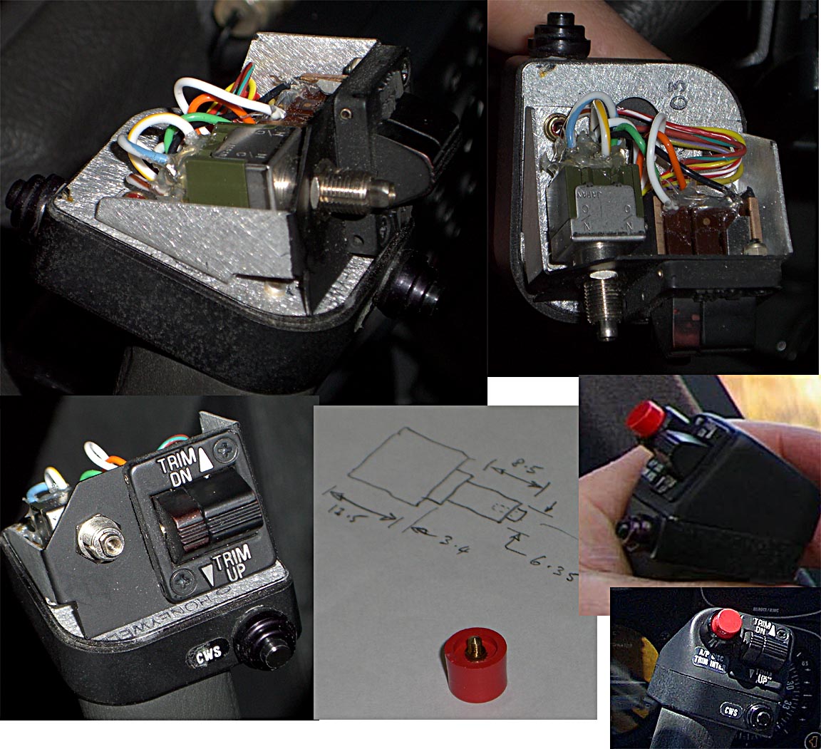
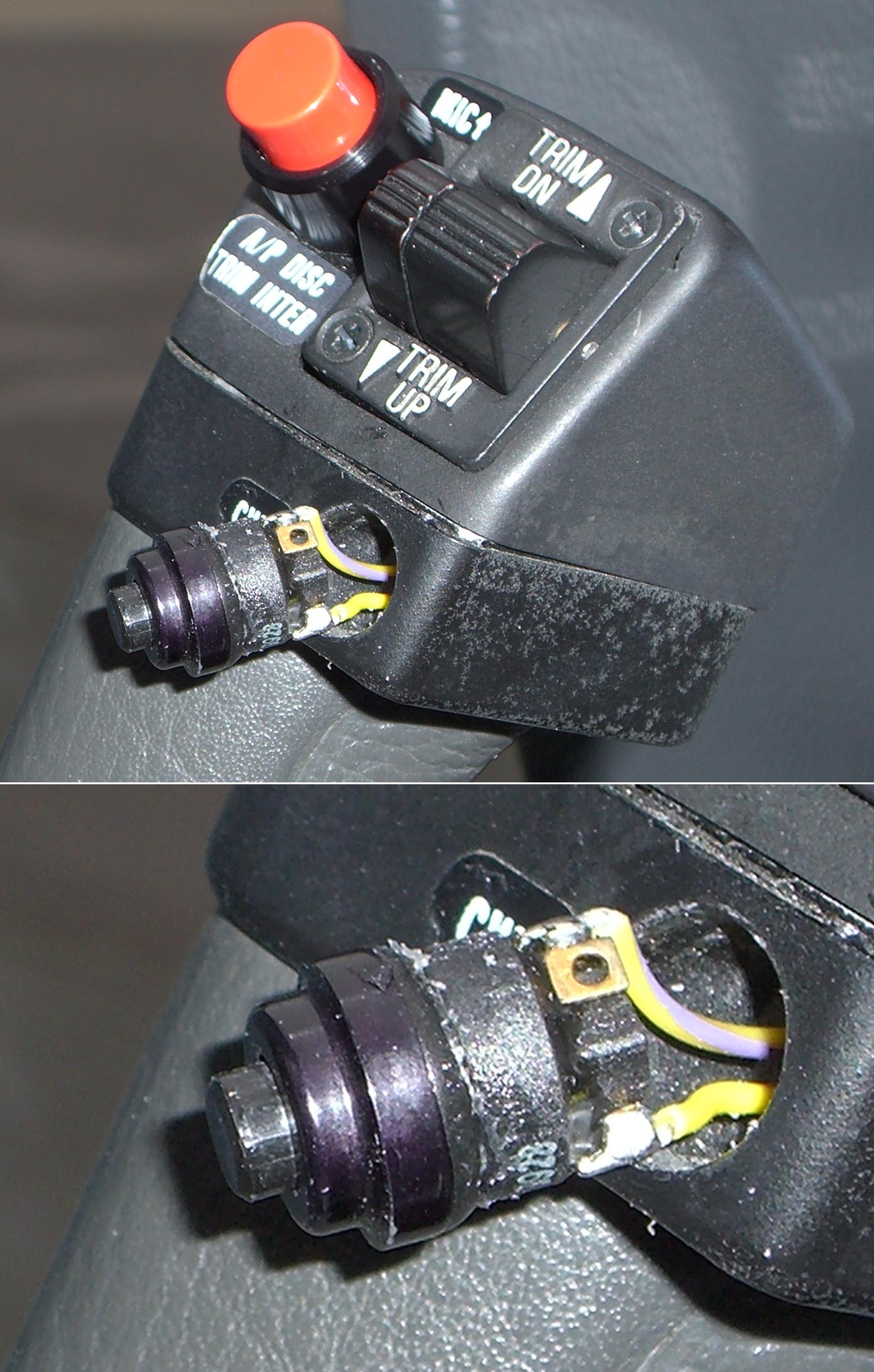
The Yoke Switch Cluster
This is implicated, usually in a non-obvious fashion, in various trim system failures, with the most common cause being the "red button switch" contacts burning up over time, resulting in the power supply to the servos being interrupted intermittently or permanently. The red button switch is way too small for the current it is switching - the three servos and their highly inductive clutch solenoids.
A picture of the internals of the switch cluster is here. A close-up of the disconnect switch is here. A close-up of the CWS switch (which is identical to the PTT switch) is here.
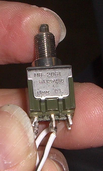
The red button disconnect switch is Honeywell P/N 031-00428-0000 which lists around $120. The actual switch is about $10 and is made in Japan by NKK; P/N including the screw-in red cap is most likely MB2061SS1W01 and the data sheet is here. A later data sheet for the series is here. It is important to specify the silver contacts as the gold ones are not rated at anywhere near enough current; this switch is not really up to the job as it is.... The switch is available from various places including Mouser.com whose data sheet page is here. Mouser part number MB2061SS1W01-BC is most likely to be stocked. The red screw-in cap is also available both separately and included with one of these switches - as shown in these data sheets.
However, the NKK switch, with its contacts rated at 3A at 30V DC, is too small for the job anyway. It is difficult to find a switch with more robustly rated contacts in this mechanical style. Honeywell make the 8N2021-014-Z which in some documentation is specified at 6A 30V DC which sounds better than the NKK one, but I have taken both types apart and the contacts appear identical... This switch fits perfectly into the available space but has a different actuator and one needs to sort out a different cap; a slightly flimsy red plastic push-on cap is available (as the data sheet shows) or one could machine something up from a red material.
There is in fact a wide range of much more robust military spec switches. Otto make a lot of mil-spec switches; this is one example (data sheet) but due to its 2A current rating it would need a relay. This one (data sheet) would be usable as a direct replacement for the KFC225 switch, subject possibly to a small modification of the switch cluster moulding, but being single-pole one would need to implement the "button pressed" signal to the KC225 computer differently.
One can greatly extend the switch life by disconnecting the autopilot using
the KC225's AP button, rather than by using the red disconnect switch ![]()
The CWS switch (which is identical to the PTT switch) is a Honeywell P/N 031-00514-0000 which lists around $120. It is a high quality mil-spec switch. The switch is made by Otto and is a variant of this one (data sheet). The P/N is most likely P7-116122 and it costs around $20. An almost identical and widely used switch is another Otto model P7-126121 sold e.g. by Sigtronics but this one has a red plastic actuator. These switches almost never fail. Update 12/2013: The Otto P7-121122 (available from mouser.com for about $25) has been reported as being identical to the PTT switch.
The trim switch cluster is Honeywell P/N 300-09744-06501 and this includes all the switches and the mounting plate. This lists around $700. If the trim switch needs repair, this is perhaps the only legal means of doing that. The individual switches are only cheap $5 off the shelf microswitches though...
-0500 roll servo - a marginal fix?
It has been claimed that an alternative roll servo that can be used on the TB20, the 065-00179-0500 - KS271C, burns out less often, but has been known to suffer from occassional roll axis oscillation. This is not a straight replacement for the -0200 however; the KC225 autopilot computer requires a different configuration uploaded into it. This process uses what Honeywell call a "certification file"; these files are uploaded into the KC225 during a config mode which is done using a laptop acting as a dumb terminal. I do not have these config files and have not been able to find them. In the UK, only about 1 avionics shop has these and can do significant KFC225 work. I think any difference in the -0500 burn-out rate is illusory and just an artefact of the smaller numbers installed.
The Way Forward?
The best thing would be to press Honeywell to fix the system, but they have very deliberately ignored the issue for 10 years so this is not likely to work.
The KFC225 failures tend to be confined (if that word is appropriate) to the following areas, with the most common at the top:
1. Roll servo burnout
2. Pitch servo burnout
3. Pitch servo torque sensor failure (broken strain gauges)
4. Pitch trim servo
5. Barometric sensor in the KC225
6. Accelerometer in the KC225
The first three are very common. The last three are very rare.
In the absence of co-operation from Honeywell there is no legal fix for anything - other than replacing complete servos as they fail.
One can make maximum use of "exchange overhaul" units sourced from
US mail order outlets such as South East
Aerospace who offer a very good service, albeit with absolutely rigid adherence
to the warranty fine print ![]() However there is no assurance that the motor or the tachometer in an overhauled
unit has been changed, so for the $2000 you could be getting a unit which does
not have far to run...
However there is no assurance that the motor or the tachometer in an overhauled
unit has been changed, so for the $2000 you could be getting a unit which does
not have far to run...
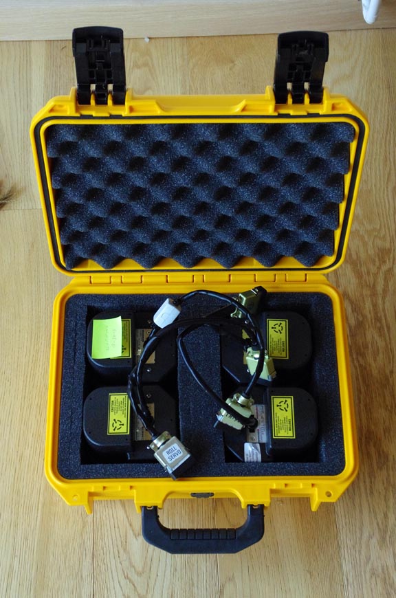
Nowadays, I fly all long trips with a box with spare servos (purchased new or overhauled, with 8130-3 forms) in the back of the aircraft. Ridiculous? Yes...
DO NOT Install SB11
This is a bodged modification which was never properly tested. Refuse to accept any SB11-modded servo.
Installing TCAS or a RADALT?
I would recommend that anyone installing a radiating system (e.g. TCAS, RADALT) gets the installer to use the very best cable for all RF wiring e.g. the double-shielded RG400. There is a very obvious correlation between these systems and high rates of servo failures. Here are some notes on a TCAS installation.
One would expect a DME or a transponder to have a similar effect but perhaps not... In the TB20, the underside TCAS antenna is sometimes installed very close to the roll servo.
KI256 Vibration
In early 2012, Honeywell Europe contracted Avionics Straubing (a well known German avionics shop) to look into the widespread problems. The shop did not make any apparent progress but did make the bizzare discovery that vibration of the KI256 horizon (which acts as the pitch and roll reference for the KFC225 system) is being transmitted directly to the roll servo (KS271C), causing the motor to be driven with some spurious waveform.
Straubing have not replied to queries. While I believe this vibration alone is unlikely to create an extended current limit condition (with the eventual destruction of the servo) it would not help with the life of both the motor and the tachometer. This would seem to be really stupid software design, but is totally plausible when looking at the videos further back in this article showing the garbage signal coming out of the KC225 computer.
From November 2012, Socata are offering a new instrument panel rubber mount kit
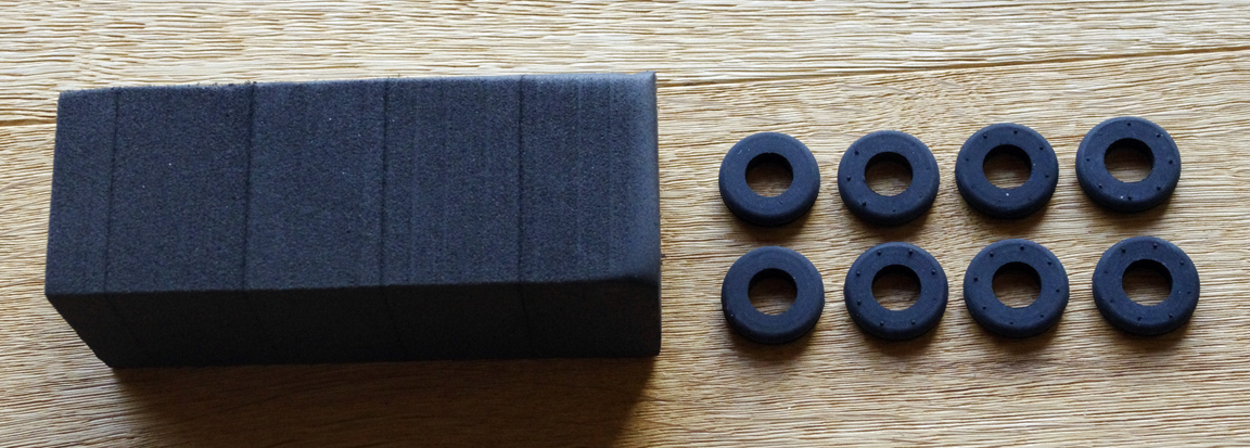
P/N OPT10930500, for about €100. This includes foam spacers which go between the LH and RH clusters and the centre stack; these are supplied in the form of a foam block which you are supposed to cut the required pieces from. The TB20 centre stack is not rubber mounted and if the LH or RH clusters are touching it, vibration will be transmitted to them. And if the LH or RH clusters are not touching it, they tend to vibrate horizontally by quite a bit.
Also included are 8 rubber grommets which are supposed to be pushed over the existing rubber mounts. 8 is enough for the LH instrument cluster, and something similar is needed for the RH cluster if any similar horizon is installed there. These grommets may do something useful, with a bit of luck. They will stiffen the rubber mount, changing the instrument cluster's resonant frequency. This drawing which comes with the kit shows the suggested use of the parts. The grommets are made by a French company as shown here. The actual grommet is DA-120-180-10 which is shown highlighted on page 4 of the PDF. There is nothing notable about these except possibly the material chosen for its temperature range. These grommets cost £12 for a bag of 100, from SES-Sterling Ltd +44 1952 582287.
The foam is LD24FB (local copy English brochure) from Zotefoams and appears to be 4.5 x 30mm sheets glued together to make the above block. It appears to be a foam commonly used in Airbus assembly. But there was no need to glue together several sheets, because the piece (Qty 4) actually needed is about 50mm x 50mm x whatever thickness will push-fit into the gap, which is about 3-5mm.
This modification is definitely worth installing because the panel vibration is visible on the KI256 flight director, and while I did not see it on the pitch/roll indicators it's possible that it is present on the pickup coils which drive the KFC225, due to internal resonances within the instrument. However I am 100% certain this "panel vibration reduction" is not anywhere near the whole story. The pitch servo appears to be excluded from this failure mode hypothesis because - once the preset altitude is captured - the KC225 uses its internal barometer and accelerometer to control pitch. But the pitch servo remains vulnerable to this issue during climb or descent, and most of my servo burnouts in the last few years have been pitch servos, and mostly in cruise flight... Also there is no explanation for the repeated failures over the same location in France, etc, etc.
The grommets do reduce the visible KI256 vibration but of course any long term effect will not be apparent.
The installation is easy enough but the lower grommet in each vertically adjacent pair hits a piece of trim
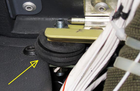
so all eight lower grommets need to be trimmed with a knife before installation,
otherwise the result is a bodge which tilts the instrument panel by about 1
degree, and looks a right mess. One avionics installer managed to bodge them
in regardless, which is how I got the above pic ![]()
Ferrite Filters
A number of KFC225 owners have clipped a common ferrite filter onto the servo cable, and there is some evidence that this reduces the burnout rate. One example is this one (RS Components 260-6492). In fact filtering is very easy to add; a "comprehensive" filter (example; a 15-way version would be needed) can be inserted into the servo cable. For extreme cases e.g. a roll servo in close proximity to a TCAS antenna, the internal surface of the plastic servo case can be painted with a high conductivity silver coating (example) which is then connected to the servo chassis with a piece of wire. Honeywell already liberally pepper the servo cable connector with ferrite beads (see earlier notes) but they are far too small to stop anything below UHF...
However, I do not believe such a clip-on filter does more than a little bit, because the ultimate cause of the servo current limit condition and the resulting burnouts is in the KC225 autopilot computer. A bold pilot could try flying a suitably instrumented aircraft over that spot in France, many times, and see what happens... it's likely that a better place for filters is on one of the wires connecting to the KC225, but there is a huge number of those. The ones going to the servos are probably the longest, however...
What is everybody else doing about this?
Due to Honeywell's 10 years of stonewalling and whitewashing, KFC225 servo repair and modding - official and unofficial - is a substantial business around the world. This company sells a fair number of their KS27xC servo test boxes at $3000 each.
It is however easy to wire up a servo on the bench to test it. This is the typical schematic and these are the basic connections for testing the servo.
In a press release in 1/2011, Honeywell announced a restart of production of the KFC225, which started originally in 1999. But at time of writing (8/2012) there is no sign of anything, apart from the useless SB11 mod, which is specified for the roll servo only. One would think Honeywell would now have an incentive to roll out a proper fix and try to regain some credibility. For example Cessna, who had massive KFC225 issues on the Caravan fleet, designed-out Honeywell avionics as far as they could on of their aircraft range, and the jet avionics market must be significant to Honeywell even if the piston market isn't. But I suspect that it is too late now. There is no indication that there are any competent engineers left at Honeywell, and it is now 10 years since all OEM KFC225 customers dropped the product.
Honeywell never stopped making the servos, which is not suprising since it is a big business for them. I recently received one with a serial number of around 10,000 and looking at past numbers this suggests they have made aound 6000 of them since the last OEM customer dropped the KFC225, around 2002. Clearly, at say $2000 each trade price, making servos to replace the burnt out ones is a big moneyspinner for Honeywell - millions of $.
Why only the KFC225?
The older autopilots don't suffer from this issue on anything like the same scale.
So it's worth looking at older designs of these servos and maybe find out why they did not go up smoke as often. It turns out that the servo amplifier design, and in particular the use of the specific "bridge" output stage topology with the upper transistors hard-on and the lower ones doing the control, has not significantly changed since the 1970s. The motors have not changed, either. The crappy Globe motors have always been used. However, all the older designs from King/Honeywell used large TO3 power transistors, which could dissipate a lot of heat.
There are also other strange factors. The KAP140 (developed 1996) uses the same servos as the KFC225 (KS270C, KS271C, KS272C) whereas the KFC150 (developed 1980) uses simpler servos on which the tachometer feedback goes back to the autopilot computer (KS270B, KS271B, KS272B).
So I think two consecutive design changes have brought this about: Firstly the use of fully-overmoulded (thermally flimsy) "power" MOSFETs, which came in for the KAP140. Secondly, the KC225 "digital" autopilot computer's defective software which controls the aircraft nicely but (as noted higher up above) periodically throws in spurious waveforms.
The amplitude of this waveform is obviously within the "mechanical play" in the servos because the autopilot failure and servo burnout is not evident (via strange flight behaviour) until the servo is burnt out.
What I don't know is whether the KC225 might exit that "spurious waveform" state by itself. Normally, of course, the pilot, upon seeing the aircraft is out of control, will quickly reach for the red button and then disconnect power to the autopilot. In all such cases I have found that the autopilot was gone. Not always totally burnt out, but functionally gone.
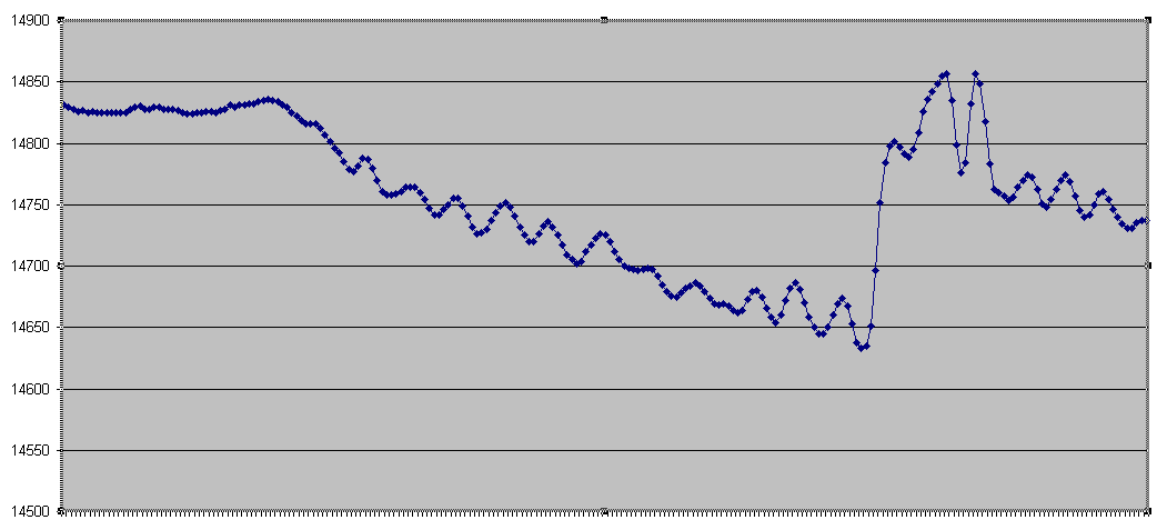
Update 5/2016: I am pretty sure the KFC225 does exit that spurious waveform by itself. This is very difficult to notice because it happens statistically very rarely but I do recall that just before the pitch servo would burn out, there was a loss of altitude - about 50ft. I have just managed to capture this on a video:
Plotting out the GPS altitude, over a 15 minute FL070 section of the flight above, shows this
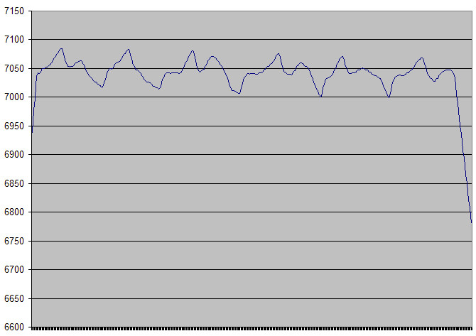
which shows a really obvious periodic behaviour, with a cycle time of about 2.5 mins. The x axis above is 15 mins long.
Why are there some KFC225s that appear to work?
Some TB20GT owners claims theirs work OK, and a larger percentage of non-Socata KFC225 owners find the same. I suspect that whatever makes the KC225 to go berserk and blow up the servo(s) is external RF, which most likely is coupled via wiring, and this is installation-dependent.
However there is another factor: many owners lie, because they don't want to
undermine their resale value. I know of a TB2x aircraft which barely managed
30 hours between servo burnouts during the year immediately preceeding a sale
to an unsuspecting buyer, whose seller told prospective buyers that there were
no issues. Presumably the avionics shop which changed all the servos (under
the Honeywell extended warranty) was typing up logbook inserts, which
the seller "forgot" to glue into his airframe logbook ![]()
How did Honeywell fcuk up so badly?
The more I look into the avionics business, the more I see a worsening lack
of design competence. This is not suprising as the business delivers little
innovation so smart people move on soon. On top of that, Honeywell has abandoned
the GA avionics business around 2000... I don't think they have any engineering
resources left today. They might have old old geezer left in there who is snowed
under with paperwork, in between checking his current pension fund valuation
![]()
A Different Autopilot?
For a complete change of autopilot, the STEC 55X is by far the most popular retrofit product, but it does not use a direct pitch and roll reference and therefore its performance is not anywhere as good as the KFC225. In flight, in any turbulence, it rolls around a few degrees when the KFC225 would have been totally straight. I have flown with a 55X in an SR20 and it was all over the place, in roll. Also it sometimes suffers from stability problems such as marginal pitch stability under certain loading conditions - unsuprising because the sheer number of different STCs could obviously not have been obtained with flight testing each STCd aircraft on the edges of its flight and loading envelopes.
Also, STEC servos do fail, and replacing them is far harder than replacing the Honeywell ones, because the bridle cable has to be removed and reinstalled / retensioned.
Future options might include the Avidyne DFC90 which conveniently uses STEC servos but Avidyne are slow in getting it STCd for aircraft beyond the original pre-G1000 Cirrus models.
STEC have announced that driving their servos from a non-STEC autopilot computer invalidates the STEC warranty, and that STEC will not even repair out-of-warranty servos if they have been installed in such a system. This is going to make life very difficult for Avidyne...
Avidyne have announced they will be developing new brushless-motor servos, mechanically compatible with the Honeywell mounting i.e. they are abandoning the S-TEC servos. This is a good idea, but nowadays Avidyne are a company which talks and talks and is extremely slow at delivering new products. It is most likely these servos will work only with the DFC90 autopilot. In August 2013 Avidyne announced they abandoned that project and instead will try developing their own servos. In July 2014 they said this project is running very slowly and nothing is expected in 2014.
The best current system appears to be the Garmin GFC700 but this will never be certified for the vast majority of aircraft that have the KFC225 installed.
I think the best option for KFC225 owners is to stick with it, while developing a usable strategy for dealing with the servos...
KFC225 Calibration
This note describes some of the operations involved in adjusting the KC225 autopilot computer. This may be necessary if e.g. the KI256 horizon has been replaced. There is no need to do any of this if only a servo has been changed. Very few avionics shops have this capability; only 1 in the UK for example.
On a newly installed system, a number of operations need to be performed which are beyond the scope of a little web article like this. One needs to use a Honeywell dealer with the KFC225 system approval. However, for subsequent adjustments, things are a lot easier, largely because the KFC225 is a digital (software controlled) autopilot, is self contained, and does not need complicated tweaking.
As mentioned in the Feb 2009 update above, most settings are accessed via an RS232 link with a laptop, but an existing installation will rarely need these to be tweaked because most of them are stored in a separate configuration module so if the KC225 computer is changed, the configuration is loaded into it automatically. This is especially relevant for loading a so-called Configuration Diskette which specifies the control loop parameters; this is available only to KFC225 dealers and despite some efforts I have been unable to get my hands on one... but luckily the data resides in the configuration module. Only if this module got trashed would one need to find a suitably equipped Honeywell dealer.
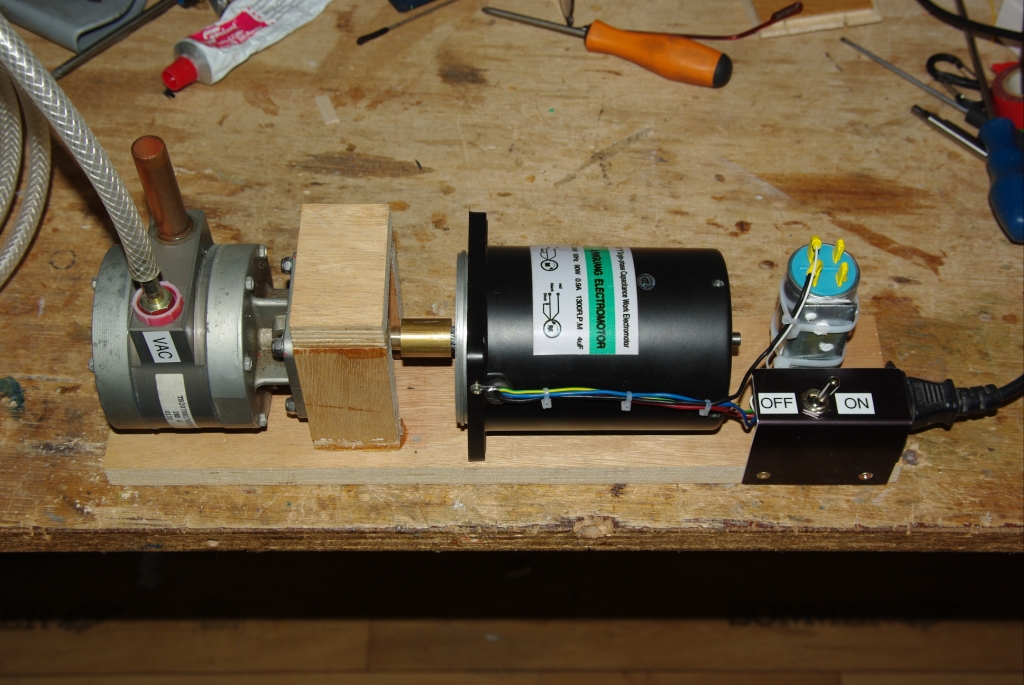
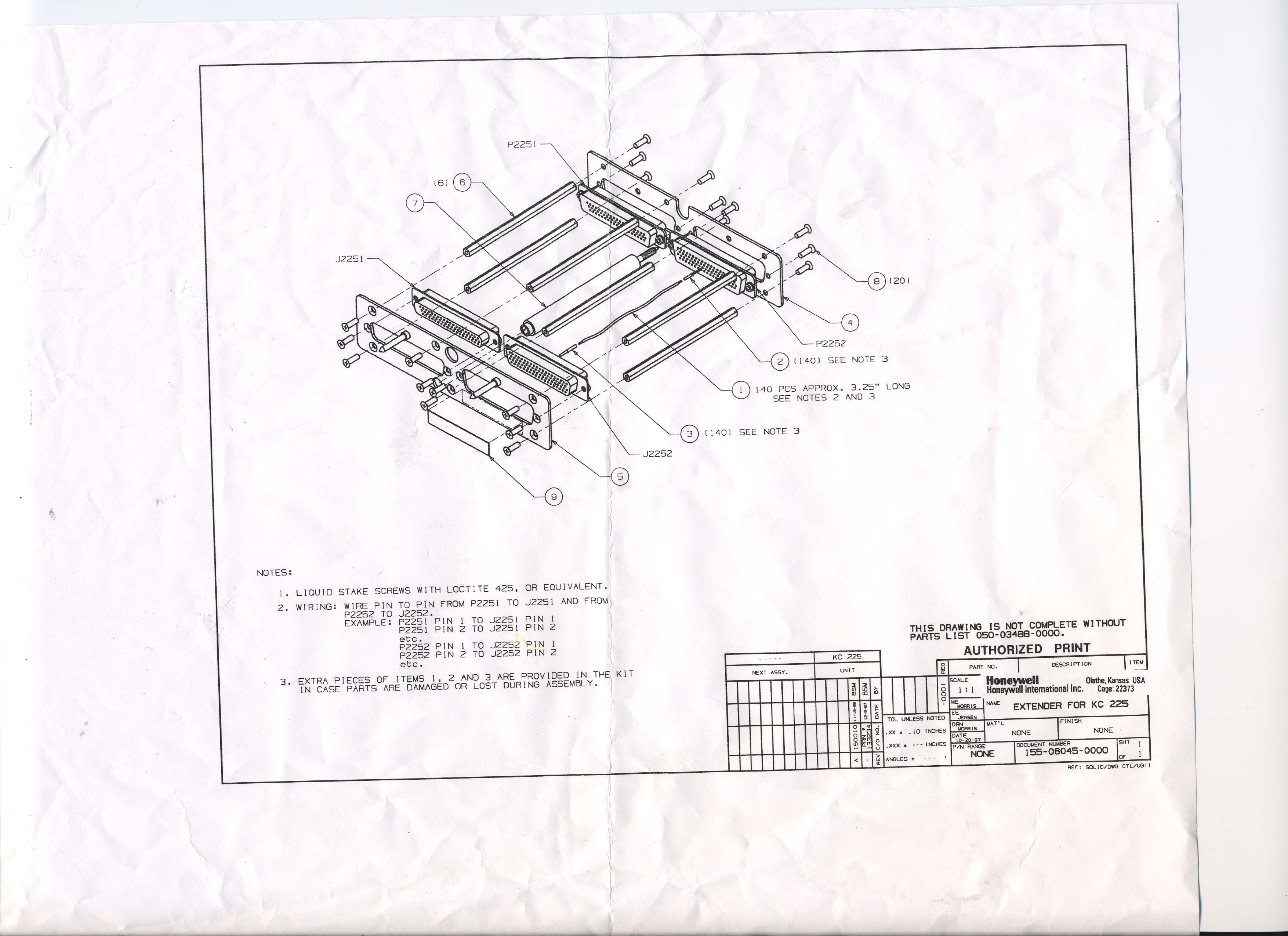
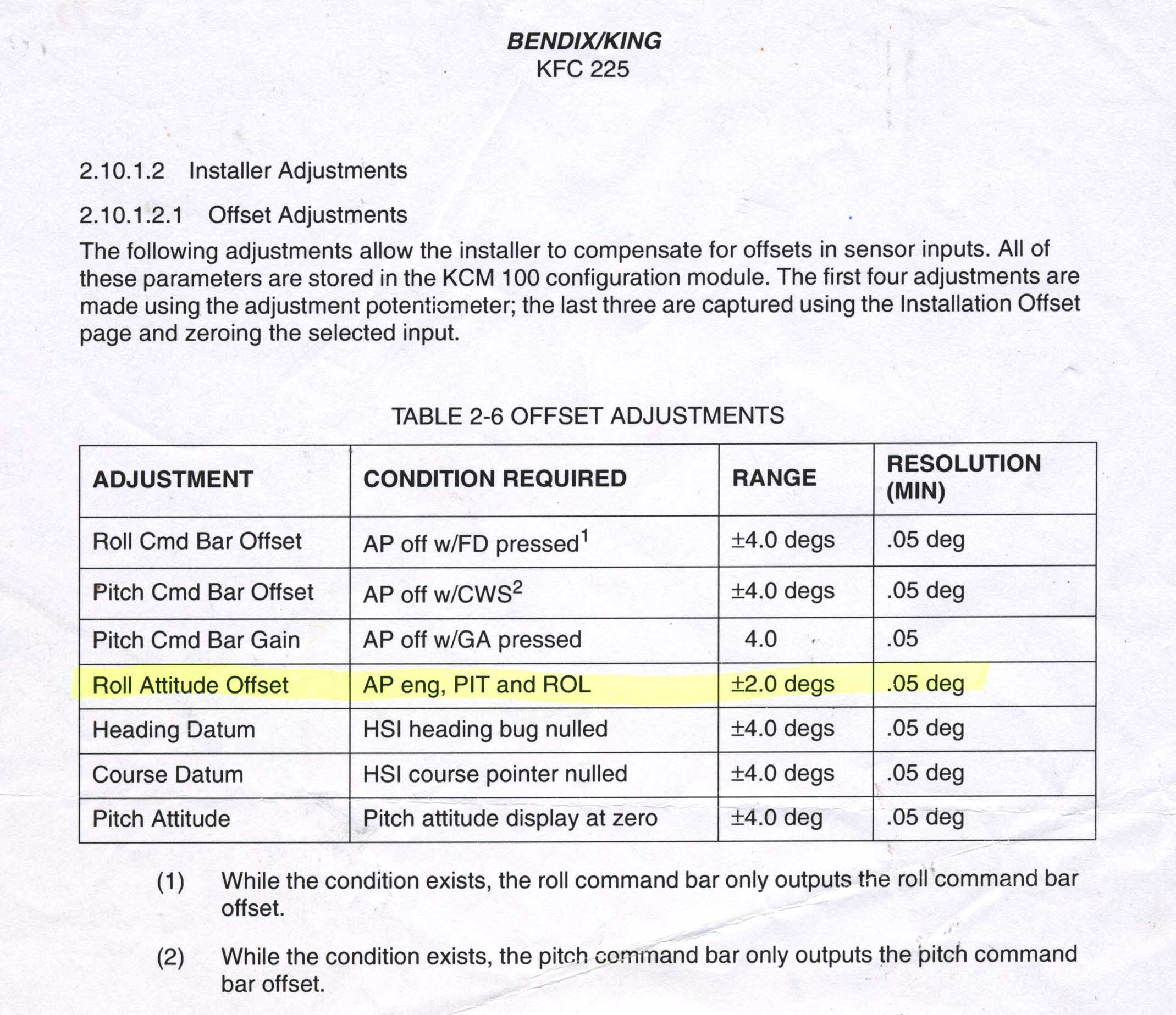
A different long term issue with the KFC225 system is that most installations are using the KI256 vacuum horizon, whose reliability is highly variable depending on its history, who last overhauled it, etc, and is probably comparable to the reliability of the vacuum pump! The KI256 costs between $11k and $24k to buy new although an overhauled exchange unit can be sourced for about $3k (2010 prices from the USA). My last one came from Castleberry Instruments in Texas; I can highly recommend them for both customer service and the accuracy of the unit they supplied. If the KI256 is changed, the KC225 computer needs to be recalibrated in pitch and roll, which involves accessing two trimpots in the side of it. This is a stupid design feature on an otherwise fully digital and RS232-configurable product... To gain access to these trimpots while the KC225 computer is in situ and running (on the ground) one needs a vacuum source (to erect the KI256; normally this is a vacuum pump driven from a standard electric motor - example) and also a special Honeywell bus extender which costs $1400 or so. Mains power driven vacuum pumps are common on the avionics scene but very very few Honeywell dealers have the bus extender and those that don't have one don't want to do KFC225 work... I have this extender; it was bought between two KFC225 owners who shared out the cost.
Other Stuff
When replacing a KI256, always source a Mod 11 unit because they are much more interchangeable (in terms of whether the KC225 recalibration is actually required) than previous KI256 versions. With a bit of luck, you may need only to tweak the roll null which is done in flight with a small pozi screwdriver using the KC225 front panel accessible pot.
Some notes on how to get rid of the KI256 completely can be found here. None of them are easy or cheap though and some (e.g. having a switch+relay to switch between the KI256 and the Castleberry electric horizon) would be difficult to certify, not least because the KFC225 AFMS would need updating and certifying. The new King KI300 may be a better option for those who don't want to do a major refit.
The strain gauge assembly can be repaired by Sensor Solutions Ltd for around £100. The four strain gauges are fortunately very common types.
This 2001 document (found in 2025) shows the problems were known to Honeywell way back then. It details a bizarre test in a freezer, to see if a particular KC225 has a fault.
Page last edited 1st January 2026
Any feedback, reports of dead links, corrections or suggestions much appreciated:
Contact details
