Shadin Fuel Flowmeter
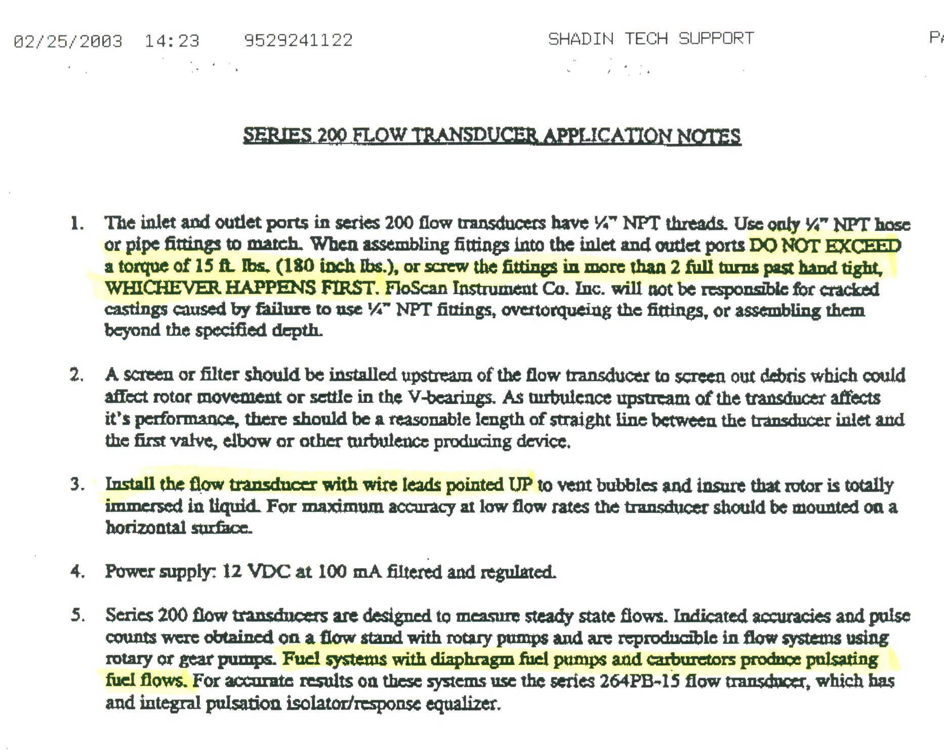
Introduction
This article describes a long and frustrating process involved in investigating and fixing an incorrectly reading aircraft fuel flowmeter/totaliser system.
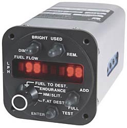
The subject is a Socata TB20 GT aircraft which has been fitted with a Shadin fuel totaliser. The system comprises of a panel mounted flow computer (made by Shadin) fed by a turbine flow rate transducer (made by Flo-Scan, P/N 201). The Shadin unit also supplies a +5V DC supply to the flow transducer. The Shadin also feeds a GPS which can then project fuel remaining at the end of the current flight plan (assuming present power setting and other factors remain constant).
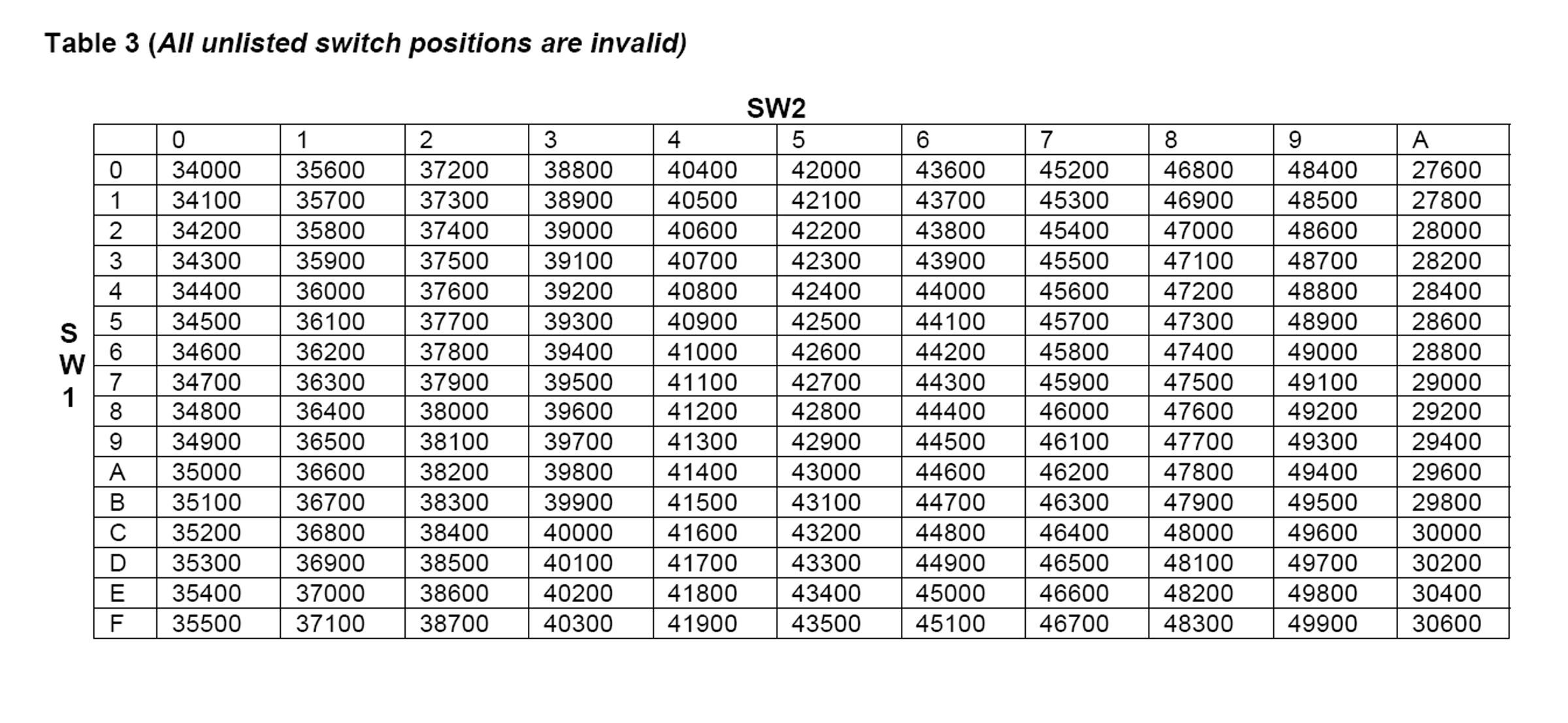
The factor with which the flow computer converts the incoming pulses is called "K factor" and is adjustable using two 16-position rotary hex switches on the side of the Shadin.
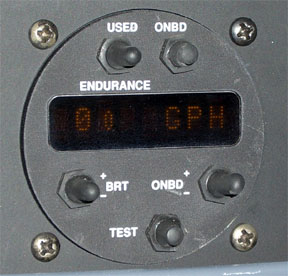
The TB20GT Shadin flow computer 912080-38C
does not appear to be a standard Shadin product but according to Shadin is a version of their Microflo originally modified for the Socata TBM700. However very recent TB20s appear to have the standard Microflo-L like this one.
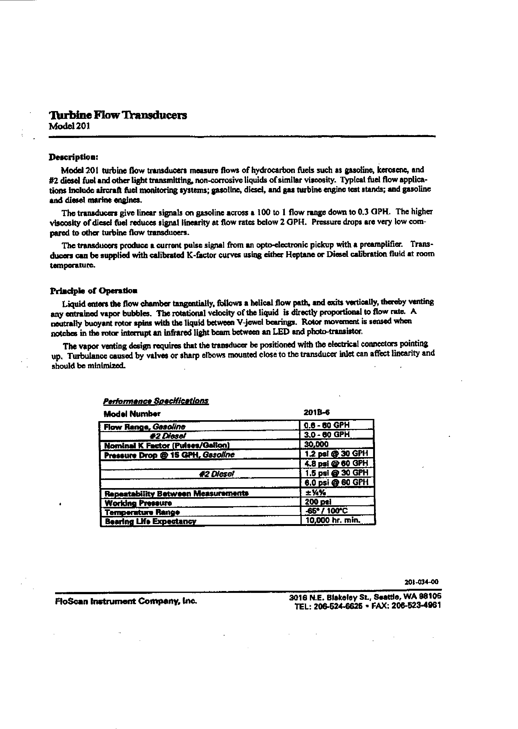
The flow transducer is made by Floscan, part number 201B. The data sheet on it is here: page 1 page 2. Floscan make these products mostly for the boat market. The transducer appears on their website here (local copy) and they have been making it for many years. In the aviation market, it appears to be resold mainly by Shadin. The following pic shows the 201B transducer exposed, without any fire protection sleeve:
Note the above pic is not from the factory TB20 installation; in that installation the transducer is in the belly of the aircraft. Each unit has an individually calibrated K-factor which is engraved on the side. Mine has "298" which means it generates 29800 pulses per USG. It is not known what fluid this is done with (Floscan and Shadin have never answered this question) but one would hope it is Avgas!
The page from the TB20 maintenance manual which shows the Shadin instrument and transducer wiring is here. The transducer is fed with +12V (this is unverified on the one I have although the Microflo-L manual gives this figure) from the Shadin instrument and it's open-collector output (no pullup is in the transducer) swings up to whatever the internal pullup in the Shadin instrument is connected to; +5V in my case. The waveform is a very roughly symmetrical square wave (see below).
Performance Problems
Many owners (including myself) of new (which probably means S/N 2000+, year-2000+) TB20s have the Shadin and have reported problems. These can be summarised as follows:
1. The new aircraft is delivered with the Shadin system reading wildly incorrectly (e.g. myself and one other has reported an initial error of 25%). The customer needs to do his own K-factor adjustment but the value which is required is a long way from what should be required (around 30,000) by reference to the Flo-Scan transducer data sheet. Unfortunately, a straight calculation of what the new K-factor should be does not eliminate the error by the expected amount and one has to fiddle about several times. Here in the UK, a pilot cannot legally change the setting on the instrument so a flight to the dealer is required.
2. The Shadin reading is substantially affected by the electric fuel pump. Various explanations for this have surfaced:
2a: The flow transducer is situated in series with the electric fuel pump but not outside the fuel pump bypass valve loop, so whenever the fuel pump output pressure is less than required by the engine (which is basically always) there will be some fuel returned by the pressure relief valve. This would of course be a nice simple explanation. However some experienced Socata maintenance engineers say there is no bypass, whereas other aircraft engineers say there must be a bypass and "every" electric fuel pump has one somewhere.
2b: The electric fuel pump emits radio frequency interference (RFI) which either is picked up by the Shadin unit and counted as extra flow pulses or somehow affects the flow transducer itself.
2c: The electric fuel pump creates turbulence in the fuel flow which adversely affects the accuracy of the flow transducer.
3. The reading fluctuates periodically. Myself and at least one other pilot can confirm this behaviour. The reading is steady but every 10-20 seconds it jumps up some 20-30% and then gradually drifts back towards the steady state value. The primitive analog fuel gauge fitted to the TB20 does not show these fluctuations and the engine runs smoothly. One candidate for this is interference from a transponder or DME; some TB20 pilots (including myself) have found that the electronic oil pressure indicator reading falls to zero whenever one transmits on certain VHF voice radio frequencies. These periodic fluctuations make it very difficult to do the GAMI test (for matching up the fuel injectors) for example.
4. The reading fluctuates all the time but settles down after an hour or more. This could be due to engine operation in conjuction with the behaviour of the fuel injection unit. It is impossible to troubleshoot this in the air because so many factors cause variations.
5. The Shadin fuel computer itself does not reliably store the newly-set FOB figure. This has been reported by many users of Shadin products, not just those fitted in TB20s. Sometimes I have to set the FOB 10-20 times before it will hold it. After a large amount of my time wasted on communications with Shadin like this one where a detailed question repeatedly yields an "answer" from someone who did not even try to read the question, Shadin finally found a software bug. One work-around appears to be to wait for at least one minute after setting the FOB, before powering the unit off.
I've had all of the above problems. It was due to some pilots being in touch over the internet that enabled some others with these problems to be located. These however are only a small % of the total post-S/N 2000 TB20 pilot population.
Attempting to solve problem #5 resulted in my Shadin fuel computer being changed FOUR times (fortunately under warranty). One of these four units also failed within 2 weeks, by going to sleep (display off, no RS232 output to the GPS) intermittently.
Socata France have not commented on these issues. During a factory visit to Tarbes in August 2003 I have explained it to a very courteous individual in engineering but there has been no feedback at the time or since. The UK dealer didn't know anything about it either. Clearly, everybody in the supply chain was hoping that if they fob off the owner for long enough, it will be forgotten.
Investigation
The "radio interference" claim is great because it enables everybody to wash their hands of the problem. The aircraft manufacturer can blame the particular avionics installation, and washes their hands of any work done locally, even by the factory dealer. The equipment manufacturer (Shadin) does the same. I decided to settle this particular claim once and for all by examining the waveform coming out of the Flo-Scan fuel flow transducer, by making a T-cable tap
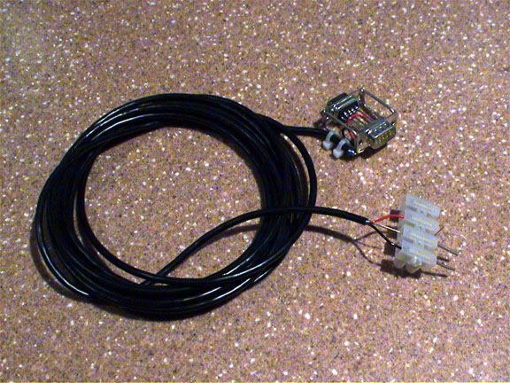
which connects into the DB9 connection on the back of the Shadin, and attaching an oscilloscope to it. This was done on the ground, with a safety "pilot" present.
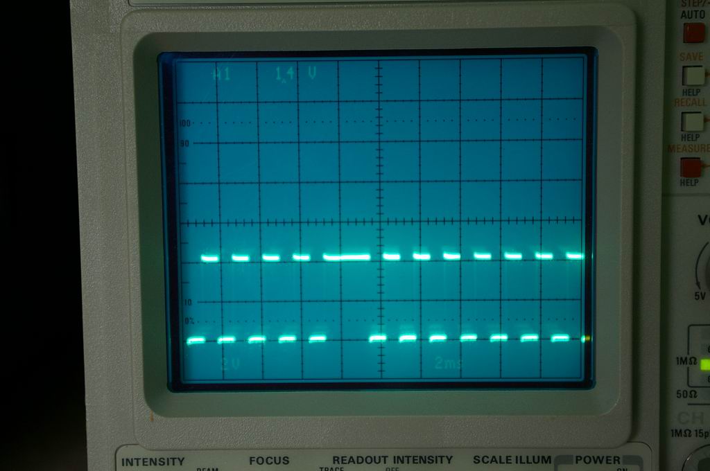
The investigation was not as conclusive as I would have hoped because it was immediately obvious that the output of the transducer is very unstable. It was impossible to obtain a stable trace on the scope, or to obtain an accurate measurement of the pulse frequency. Scope photographs would not have showed anything helpful but the following photo shows the scale of the problem
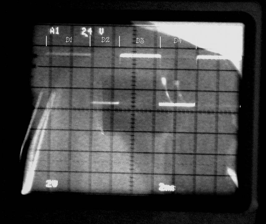
If the frequency (the indication of the flow rate) was constant, we would have the two cycles having equal lengths, i.e. D1+D2 = D3+D4. In reality there is about a 5% difference, and this is over just one cycle, i.e. over just one revolution (possibly over just half a revolution) of the turbine!! The difference between D2 and D4 is slightly more visible. The jitter would have been more visible on a movie taken of the scope display; the whole-cycle-width jitter is about 10% (peak to peak) with the fuel pump off, increasing to about 30% (peak to peak) with the fuel pump on. I could have done a movie but as can be seen, the scope was difficult to photograph due to sunlight in the cockpit. It was perfectly visible to the eye though.
Basically, it is obvious that either there is massive turbulence in the flow, or the electronics in the transducer are picking up the pulses from the magnetic pickup only marginally.
A further experiment, done at about 2000RPM, involved setting the fuel flow to 10GPH. The pulse frequency was measured with a frequency counter as 91Hz. Switching on the fuel pump increased the flow rate displayed on the Shadin to about 11GPH (but there was no change to the apparent engine power, as one would expect). Reducing the power so that the displayed flow rate was again 10GPH yielded a pulse rate of 81Hz - exactly what one would expect. These pulse rates incidentally compare adequately with the official Flo-Scan K-factor of 29000 (91*3600/10 = 32760). My actual Shadin is set to a K-factor of 34000 which does not make a great deal of sense, but it is now accurate to within 2%.
Some important matters were however established:
There was no visible electrical interference from the fuel pump, appearing in the form of extra pulses or some RFI superimposed on the waveform. Apart from the heavy jitter, the waveform was very clean (400MHz Tektronix scope). It is possible that some such RFI enters the flow transducer electronics and causes these effects but that's unlikely because we would then have to see some extra narrow or extra wide pulses (because the interference cannot cause the turbine itself to vary in speed) and there were none.
There was no visible interference from the transponder or the DME.
The explanation (which comes from Shadin, Flo-Scan and others) that the electric fuel pump alone causes the flow transducer to become erratic may be true to a degree but does not explain the problems which remain when it is not running. The frequency instability is seen at all flow rates, from engine idle (3GPH) upwards. The pump does however cause a massive variation in the pulse rate for a few seconds, of the order of 5x to 10x the steady state rate.
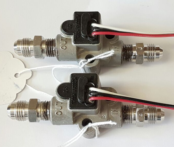
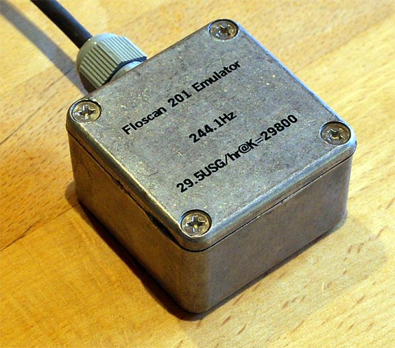
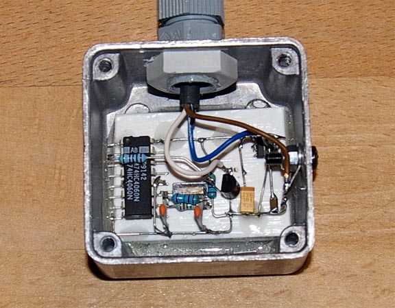
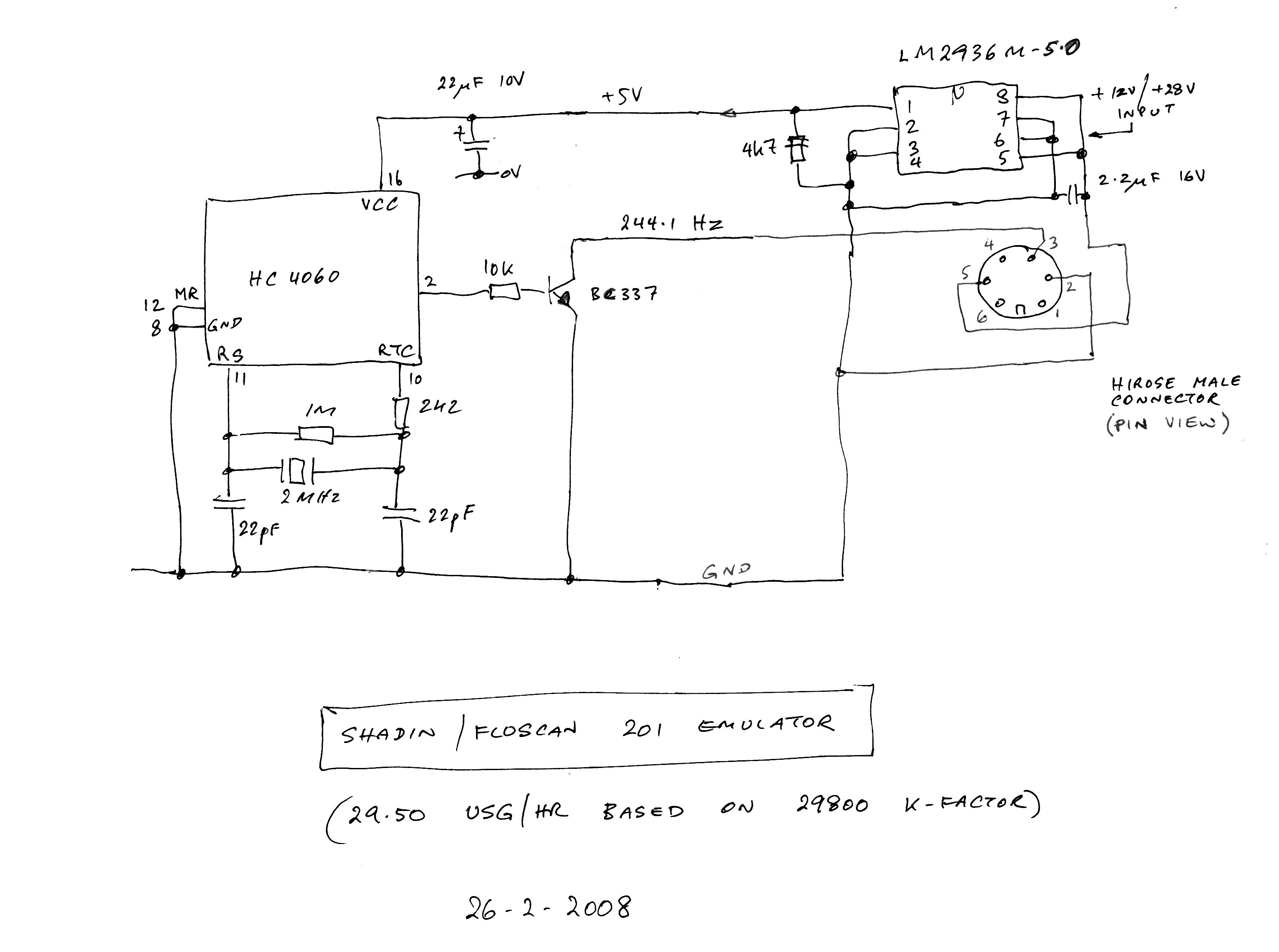
The accuracy of the Shadin instrument itself was tested with a crystal controlled pulse generator (inside view schematic) which emulates the Floscan 201 transducer characterisitics and which verified the instrument was fine.
The Socata-installed flowmeter is mounted on the cockpit side of the firewall, below the cabin floor. The pic below was taken from underneath, with the forward belly panel removed (click for larger version)
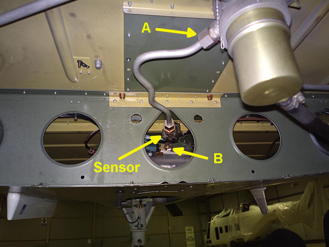
In the above location, the system does not work. There is about a 20-25% error, and it varies according to whether the electric fuel pump is running. With the fuel pump running, the reading approximates the correct reading. With it not running, the reading is roughly 20-25% too high.
When the flowmeter (sensor) is relocated to its correct place, forward of the firewall, it needs to be replaced with a single aluminium pipe which goes directly from A to B and whose P/N is further below.
Conclusion?
There is something drastically wrong with the operation of the Flo-Scan transducer.
1. It is possible that all of them are like this. Bizzare as it may seem, a look at the Flo-Scan website shows a range of their own flow indicating/totalising products and if these have integration times substantially longer than the Shadin, nobody at Flo-Scan would be aware of the problem. Most of their present product range appears to be for boats.
2. Given the transducer is being operated at 5V, and the supply voltage range is shown as 4-18V, it is possible that the transducer electronics become erratic at 5V. Maybe Flo-Scan only ever run their transducers at 12V.
3. The transducer is subjected to some kind of mechanical vibration or resonance and this affects the way the turbine rotates in its bearings.
4. There is a lot of turbulence in the flow, caused by bends in the pipework, perhaps in conjunction with engine vibration.
In general aviation, a problem can remain unfixed for years because a) very few pilots fly aircraft modern enough to have these instruments; b) there is no contact between most of them; c) many pilots will accept malfunctioning instruments especially if not primary; d) the suppliers will not volunteer the information that others have the same problem; e) most pilots pay up first and possibly ask questions later. So even bizzare explanations like 1. above are possible.
I managed to set the K-factor on the Shadin such that for the typical UK flight (1-2 hours) the error was 1-2%. However, on longer flights (say 5 hours) this increased to around 5-10%, no doubt because the actual error varies according to flow rate and on a longer flight one spends relatively less time in the climb and descent.
With zero co-operation from any of the manufacturers, the matter remained unresolved for about a year.
UPDATE 26TH FEB 2004
Someone in the USA has unearthed a very old STC which Shadin originally got from the FAA for their flowmeter, amazingly dating back to around 1981. This STC contains detailed instructions on the flowmeter location; both in terms of its location relative to the electric fuel pump and in terms of pipe lengths. A TB20 owner in the USA has implemented this STC and reports that all his problems have gone away; specifically the periodic flow rate "walkabout" and the large change in the displayed flow rate when the electric pump is in use.
More recently obtained versions of the Shadin STC are here: TB20 TB21.
It would appear that Socata either never saw this STC, or they disregarded it. I once heard (don't recall who from) that Socata had known about it but were prevented by the DGAC from mounting the flowmeter forward of the firewall. This is entirely possible, knowing some other pieces of stupidity which I have seen coming from the DGAC. However, they should still not have shipped brand new aircraft with a practically useless Shadin flowmeter system...
I believe Socata in France have been approached regarding approving a modification to enable this to be implemented on current TB20s. While this STC can be implemented if one has current Shadin-supplied (retrofit) kit, it is not legal (under the rules for usage of an STC, with the property of the STC belonging to the STC holder) to apply it to an aircraft where the Shadin system was supplied as OEM (Socata in this case) without a direct authorisation from Shadin. As noted below, such an authorisation is not a problem in this case.
The Shadin STC merely relocates the flow transducer further along what is essentially the same piece of fuel pipe. Why this should make the problems go away is a mystery. Without seeing the original design notes (which is pretty unlikely unless the c. 1980 engineer is still around and able to talk about it) it is very possible that someone just played around with hoses until it worked OK.
UPDATE 15TH DEC 2004
Despite regular reminders from me, trying to get this problem resolved under warranty, Socata France have completely washed their hands of it, and I didn't have time to give them the real hassle with phone calls which this probably called for. I have sent a total of 71 emails and about a dozen faxes in the last 30 months trying to get a resolution, discussed it face to face with Socata at Tarbes, but have received no proposals for fixing it. In hindsight I should have pursued it much more vigorously.
The aircraft is going on the U.S. register early next year which makes a lot of paperwork much simpler. So I decided to revisit the issue, even if it means paying for implementing the STC.
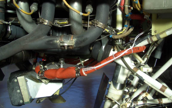
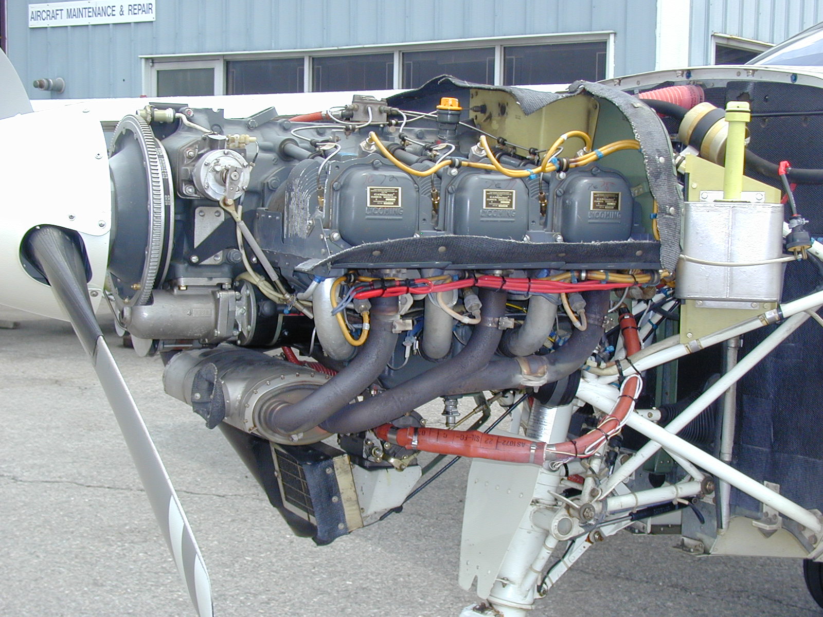
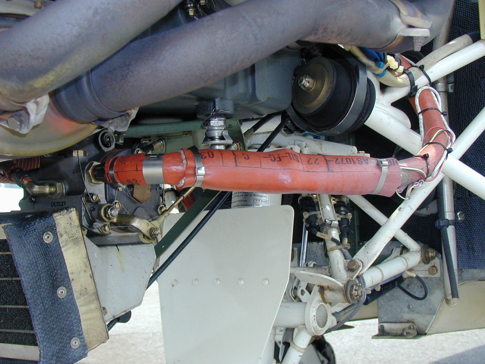
I contacted the U.S. Socata dealer (whose customer service is excellent) and they confirmed that one can apply the Shadin STC and the process is indeed simple. One needs just one additional part, a pipe P/N TB20-52024006 which fits into the old transducer location, and these pictures (taken of an aircraft in the USA) show the finished job:
engine transducer1 transducer2
Unfortunately I have lost the name of the person who sent me the above pictures. If I find it I will put in a suitable credit!
STC Transducer Installation Notes / UPDATE 5TH APRIL 2005
To date, I know of two TB20GT owners who have implemented this modification and both report that the problem has been fixed. I am now on the N register so I can get it done too.
The total requirement is:
1 x AE3660001G0054 hose (5 1/2" long) GBP 31.88 each
1 x AE3660001G0180 hose (18" long) GBP 40.33
1 x AE102-24-0070 fireproof sleeve GBP 12.92 (but see note below about size)
1 x TB20-52024006 metal pipe (approx GBP 150.00) - this goes in the original
flowmeter location
Plus a couple of jubilee clips to go around the fireproof sleeve, and a 3-core shielded high temperature cable as normally used in avionics.
The two hoses were made in the UK by Saywell International but any aviation hose shop can make them. They are Teflon and have no life limit. They have fireproof sleeves.
The fireproof sleeve P/N above (the diameter is the "24" figure) is very hard to slide over the transducer - especially if the STC diagram is followed literally and the transducer wires are routed through a hole in the sleeve which is a right pig of a job. We bought a larger size sleeve but I am not sure which exact one we got, back in 2005.
Update 20/3/2015: The Floscan transducer failed and had to be replaced. We had to replace the shorter hose because of a tiny fuel leak which could not be sorted (I suspect there was a scratch on the union and we replaced that too with a nice high quality one). Regarding the fire sleeves, I recommend ordering the following two sleeves and seeing which fits (again they came from Saywells):
1 x AE102-26 1ft fireproof sleeve £16.83
1 x AE102-28 1ft fireproof sleeve £17.83
In brief, the transducer relocation job consists of
1) Removing the transducer from its location in the belly
2) Replacing the original Socata-made metal pipe TB20-52024006 where the transducer
used to be
3) Making up two flexible hoses
4) Installing the transducer in the engine compartment, between the two hoses
5) Rewiring the transducer connections; the simplest way is to run them back
to where the original transducer was. The cable must be shielded.
The install is done almost exactly as per the Shadin STC. The hoses can be made up by any decent aviation hose shop and the modern Teflon version is preferred due to its virtually infinite life.
You have to be careful to not over-tighten the fittings which go into the diecast transducer body (one specification is here) and a lot of installers have problems achieving this without fuel leaks. It is therefore desirable to use a small amount of fuel tank sealant (e.g. PRC1422B) on the fittings' thread, obviously ensuring that none of it is applied to the first couple of threads otherwise it might end up inside the transducer!
NOTE: It also makes sense to use stainless steel versions of the fittings, sometimes called AN816-6C, rather than the steel versions (AN816-6) whose part numbers appear in the STC parts list and which tend to be supplied with a poor surface finish.
UPDATE 18TH NOVEMBER 2005
Finally, I've had the STC modification done. I obtained permission from Shadin to implement their STC; this is the standard thing under the U.S. STC system. It appears to have worked perfectly. Nobody can see why, because basically the flow transducer has been moved from one place in the pipe to a place further along the same pipe, but it works and the reading is now very stable. The operation of the electric fuel pump makes absolutely no difference to the Shadin reading, not even 0.1GPH.
However, a few flights and a fill-up revealed that the initially set (and Socata-recommended) K-factor of 30000 is wrong by about 7%. The instrument is under-reading. Socata's records for the aircraft serial number show that the transducer K-factor is 29800 (confirmed by the K-factor seen engraved on the actual transducer) so setting say 30000 in the instrument should yield a highly accurate installation. Unfortunately, from the indication of the Shadin instrument, the transducer is generating pulses equal to about 32000.
There appears to be another factor at play... It's easy enough to tweak the K-factor in the instrument, but in my case I can't set the required value of about 32000 because the particular instrument type doesn't have any settings between 30600 and 34000! So I have set 34000 which as expected results in an error of about 7%.
However, it turns out that the modification was not done quite in accordance with the STC; the transducer has been placed in the same location as the original fuel pipe; right up against the engine crankcase where it is subjected to engine vibration. I am going to get it moved to the correct position, and see if the error changes. If it does, clearly it is vibration that's doing it.
UPDATE 27TH JANUARY 2006
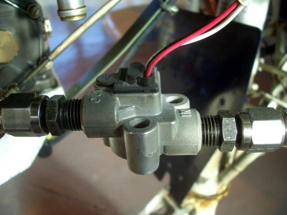
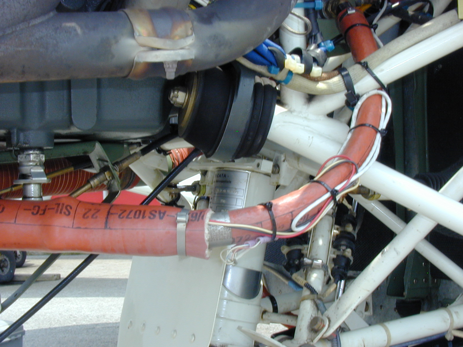
I've had the transducer moved again, as shown in the following pic that closely resembles the US installation shown above:
(Note that the above pic shows UN-shielded wiring to the transducer - this is WRONG)
The flow indication is still completely stable and the K-factor appears similar to previous. The reading is still about 7% under, checked against the airport pump, varying by about 1% either side of this, probably due to temperature and filling variations. The options are:
a) get a flow transducer (they cost $600; no guarantee this will do anything)
with a K-factor far enough away from the current value to be within the instrument
adjustment range, or
b) get a more modern Shadin instrument which has an infinitely adjustable K-factor
(e.g. the Microflo-L; needs some aircraft rewiring), or
c) construct a little inline circuit, which strips out
every 16th pulse, and set the instrument to a K-factor of 30000. This would
be legal only on a homebuilt category aircraft, of course.
11/2007
A couple of interesting documents 1 2 have arrived, on troubleshooting the system. Interesting that Shadin think that incorrect cable shielding can cause a ~ 10% error... The wiring to the original transducer location (done by Socata) is shown as shielded on the aircraft schematic, but the wiring done on the relocated transducer (done by a UK avionics shop) was UNshielded and comprised of three separate wires which can be seen exiting the fireproof sleeve in the photo above.
2/2008
For the first time in 6 years the aircraft has been grounded, due to the Lycoming crankshaft AD, and I have used this opportunity to revisit the matter and hopefully to fix the 7% error once and for all. The existing transducer was returned to Shadin who have confirmed that its "29800" calibration is correct!! I even telephoned them to double check that this check was actually done.
I have purchased a new transducer from Shadin ($600) whose K-factor is also 29800.
The new transducer was installed, together with two brand new Teflon hoses from Saywell. The installation and the hose dimensions were identical to the previous installation, except that the wiring was done completely with shielded cable. The instrument was set to K=30000 which is very close to the transducer's K=29800.
The 7% error has disappeared!
This leaves several possible explanations for the 7% error:
1) The unshielded wiring to the transducer was picking up interference (extra pulses) - despite these not being visible on a DC-400MHz oscilloscope
2) The old transducer was in fact reading 7% out - I was unable to personally verify Shadin's claim that it was fine so this doubt will always remain
3) Something wrong with the old hoses or their end fittings, introducing flow turbulence
4) The engine driven fuel pump was also changed, for a new one of the same type. I cannot see how this could have caused it...
My bet is on 1).
Shadin advise me that they rarely see a transducer producing a mere 7% error; usually it goes to zero and sometimes it does so intermittently.
It is obvious that the original problem (the ~ 25% error, before the transducer relocation) was caused by turbulence in the pipe. How did Socata get away with this? Probably two things helped: Many pilots never use the flowmeter; in some cases they found it inaccurate and just gave up using it. From about 2002 onwards, Socata have been fitting the newer Shadin Microflo-L instrument which has an infinitely adjustable (from the front panel, too) K-factor and which would allow a crude hack to be done to minimise the large initial error, and get the error to a level below several percent which most pilots would not notice. TB aircraft manufacture stopped around 2003 which took care of the problem for ever, as far as the manufacturer's warranty was concerned.
A final twist is that the Floscan 201-class transducer is simply unsuitable for the IO-540 engine. The Floscan documentation does refer to the 201 not being suitable for pulsating flows which is exactly what one gets with a cam-operated diaphragm pump which this engine has. This 3rd party manual refers to it on page 1. This Shadin document extract refers to the model 264PB-15 (which has an integral pulse damper) for fluctuating flows and a google on this P/N digs up a lot of pilot discussion on the topic. Clearly a lot of people have independently discovered this problem. Floscan too recommend the 264PB for pulsating flows. Floscan do not discuss aviation applications with users, and Shadin do not enter into communications on this specific subject. This fluctuating flow issue could very well also explain a lot of the pulse width variation seen in the oscilloscope traces above. It would be quite bizzare if the Shadin STC (which is specifically for the IO-540 engine) had been recommending the wrong transducer all along... However, it has been established over many tank refills that the system is now highly accurate - always within 1% of any airport pump whose calibration can be trusted - so whatever flow fluctuation is present gets adequately averaged by the Floscan transducer.
April 2010: I came across this document which shows the transducer installation with a JPI indicating instrument.
April 2011: I came across this document which directly states that unshielded wiring can cause the sort of over-reading which I had... I wonder if they wrote that after they saw this website?
March 2013: This article was updated with pictures from another TB20, N-reg, whose transducer was also mounted in the wrong place.
March 2015: edits regarding the fire sleeve size (in text above). The Floscan transducer failed and had to be replaced. The initial failure manifested itself as a very erratic reading between zero and 40 USG/hr, and after a few mins it dropped to zero and stayed there. This happened at start of the takeoff roll and the takeoff was aborted (largely in case it was a fuel leak).
April 2018: I came across this document from Floscan which has some useful info.
In early 2018, the transducer which was installed in March 2015 failed, with no pulse output at all. Shadin have dropped the price of these quite a bit in recent years so I bought two for $330 each. I installed AN816-6C stainless steel fittings in these, sealed using PR1440 sealant which replaces PR1422:
April 2019: For Garmin GTN (and possibly Avidyne IFD) owners: with reference to the Shadin unit at the top of this article, the data stream it outputs has been reported as incompatible. It was stated that Shadin offer a software update, which I find hard to believe on such an old unit. The later Shadin Microflo units (the ones with the rotary switch) are reportedly OK. I have not been able to verify this.
UPDATE 22 June 2023
There has been a long standing question of how to apply the Shadin STC to UK-reg or EASA-reg aircraft. The FAA STC cannot be used. There is an EASA process for validating an FAA STC for a single airframe serial number. However, it was recently discovered that there are some old European approvals:
UK CAA AAN 26779
German LBA 0366/1063
See here.
This page last edited 22nd June 2023
Any feedback or reports of dead links, corrections or suggestions much appreciated:
Contact details
