A Backup Alternator for the Socata TB20 Aircraft
This project was started in 2013.
Overview
The TB20 has a 28V system powered from a single 60A or 80A alternator, and it has a single battery.
The power supply is split into 3 buses, each with its own CB. These continue into 3 "avionics" buses - via 3 relays operated together by the Avionics Master switch - and this diagram illustrates the general configuration. But of course this division gives little redundancy, due to the single alternator / single battery power supply.
FAA Approval Issues
The installation is technically straightforward but complex in paperwork terms because there is no airframe-applicable STC for the TB20 for this (or any other) alternator, so it has to be done as a Field Approval.
If it could be regarded as a Minor Alteration, it would be easy, but this appears infeasible. FAR 43 Appendix A (local copy) uses the words "basic change" and this is very likely within that definition.
The problem for a European based N-reg aircraft is that neither of the two FSDOs that might process a Field Approval (New York, or Frankfurt) is doing them anymore.
An alternative approach is to get a DER to generate a design package with an 8110-3 form. The whole thing can then be sent to the FAA for filing, with no approval required. At least that is common practice in Europe.
Electrical Issues
The backup alternator works in a very simple way:
The main alternator's voltage regulator is normally set to 28.0V. The backup alternator's voltage regulator is set the 27.5V. Their outputs are joined together, so that normally the back alternator's regulator turns off its field current completely and the main alternator supports the entire load. If the main alternator fails, the bus voltage will try to drop down to the battery voltage (24V or so) and as soon as it passes through 27.5V the backup alternator will get its field energised and will pick up the bus and drive it at 27.5V.
The output current of the backup alternator is just 20A. However this is plenty. My entire aircraft draws around 30A, of which 8A is the landing+taxi lights, and another 5A-10A is the pitot heater. So it would be very easy to shed enough load to fly on using just the backup alternator.
Mechanical Issues
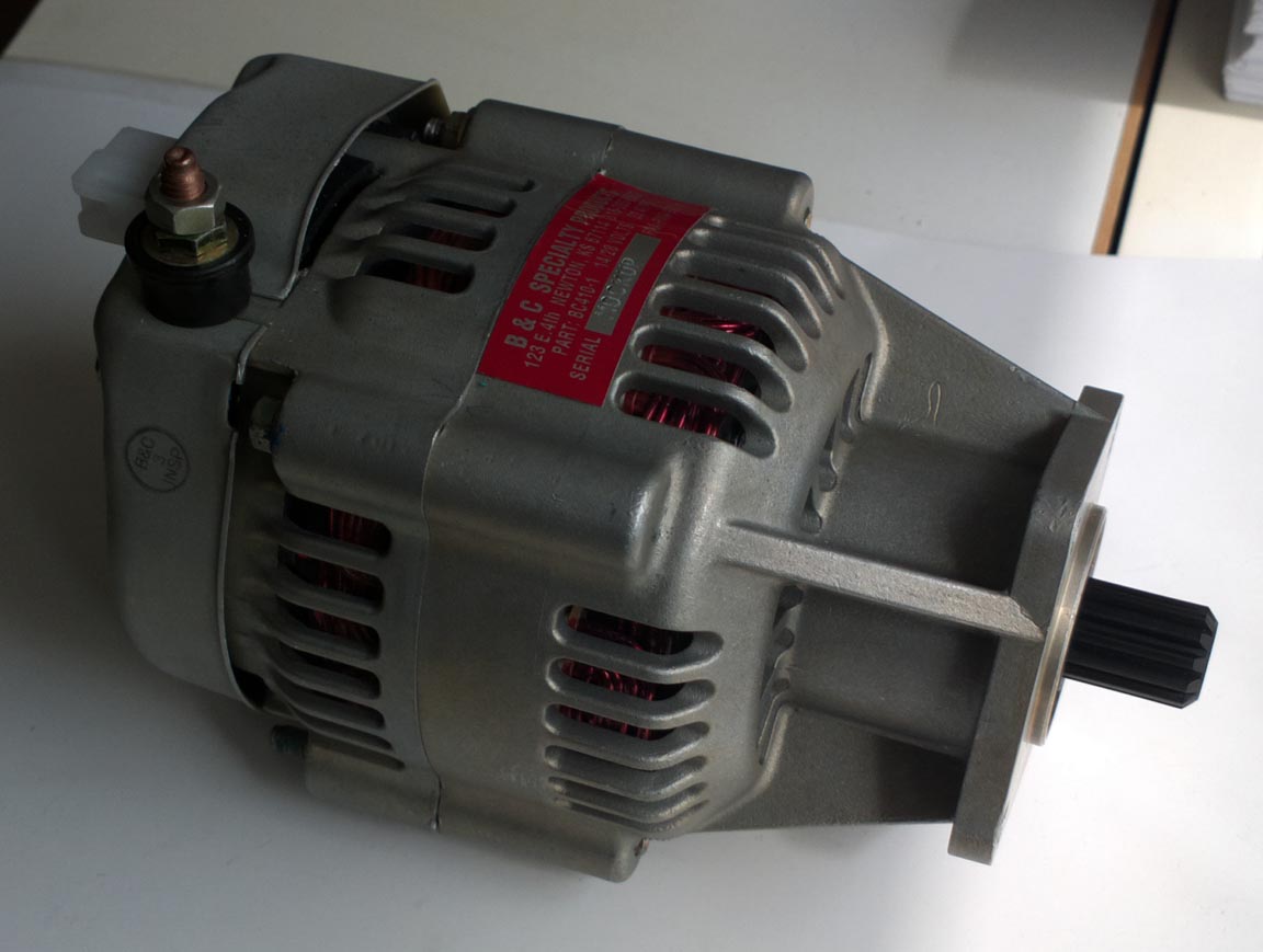
I got a "mockup" of the B&C unit from the USA, free of charge provided I paid for the carriage
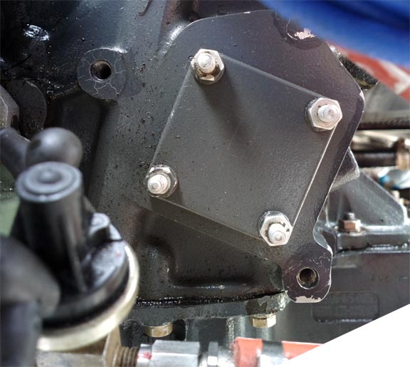
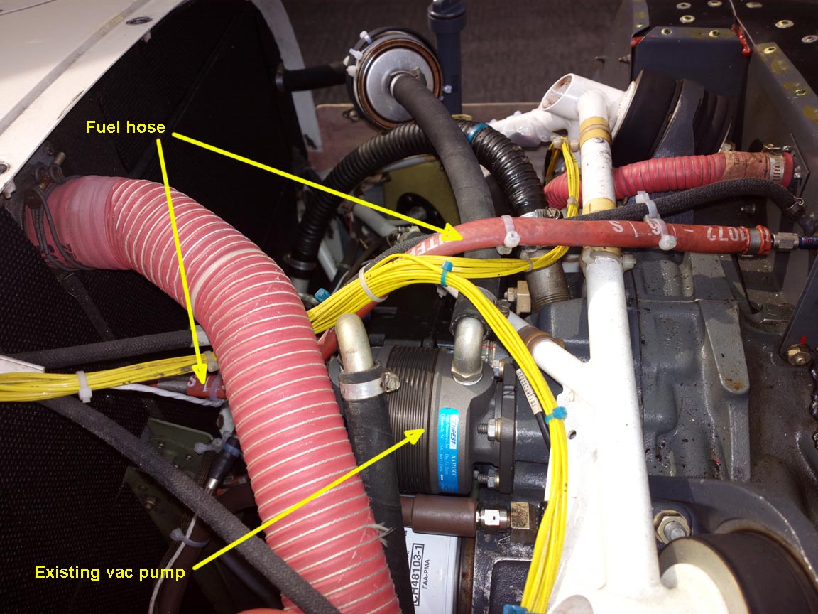
This is the spare vacuum pump accessory drive on the back of the IO540-C4
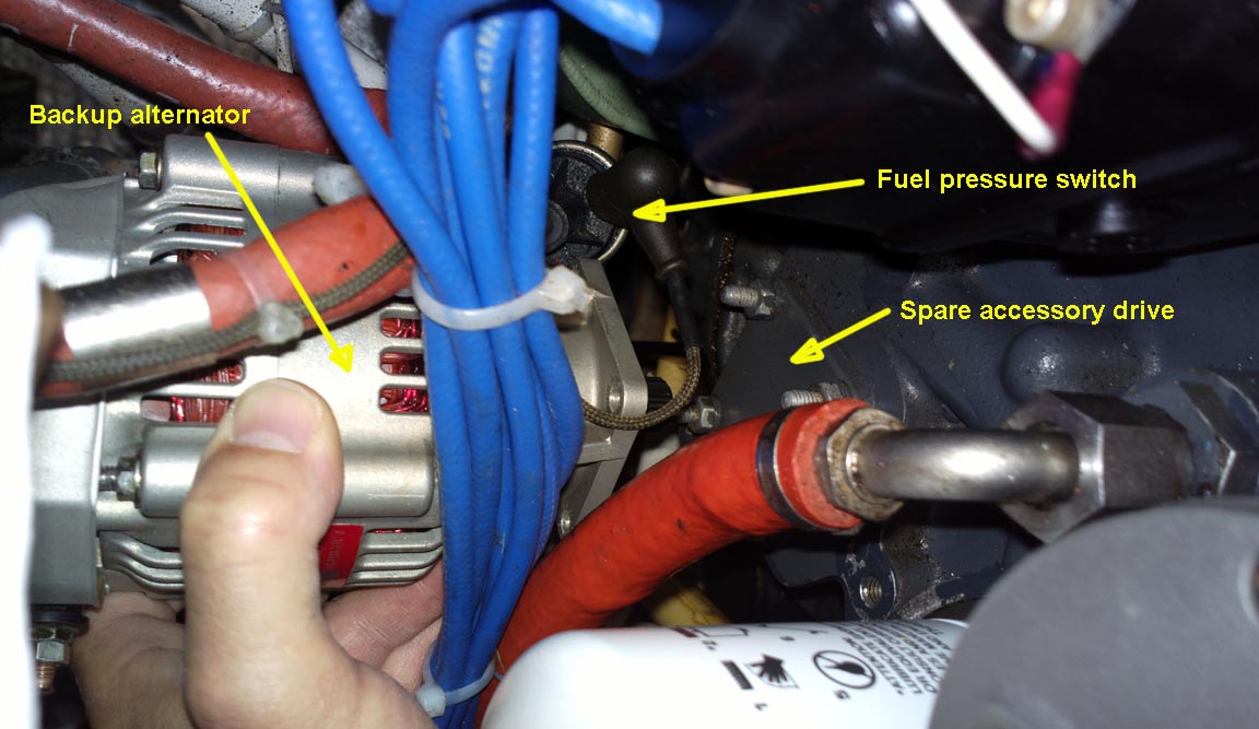
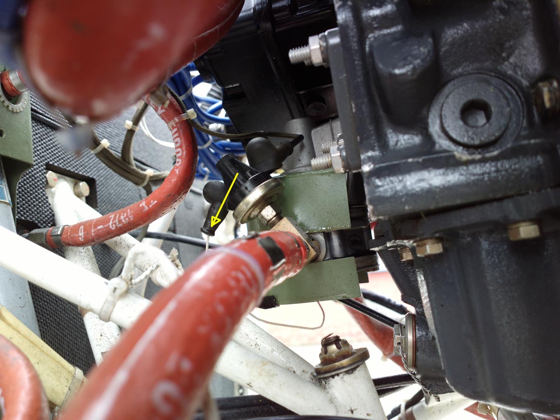
Placing the alternator into the location reveals that it hits a fuel pressure switch mounted close to the inlet of the engine driven fuel pump, which is visible in the above pic and the one below
This is the offending part
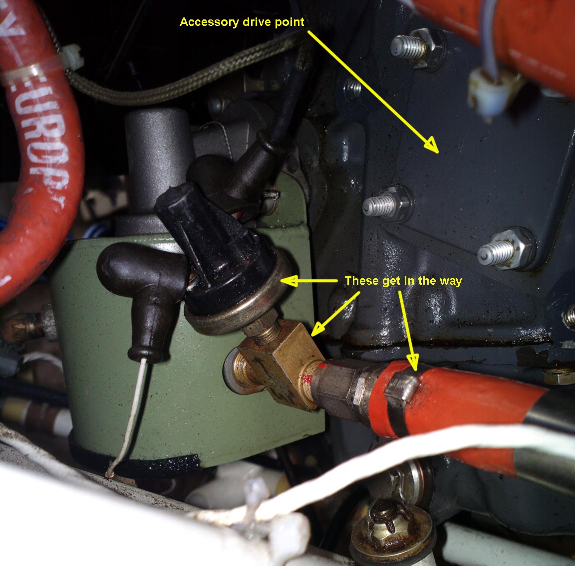
Fairly obviously one could solve this by fitting a 90 degree elbow into the fuel pump, mounting the fuel pressure switch on the inlet side of that elbow, and relocating the fire-sheathed hose appropriately (the hose may need to be longer).
It has been suggested on another site that fitting this alternator in the TB20 needs the existing vacuum pump
to be moved to the spare accessory drive location, and mounting the alternator where the vacuum pump used to be. But that cannot work since the diameter of the vacuum pump is still too great and it would also hit that fuel pressure switch. So it doesn't sound like anybody has actually done it...
The alternator could be mounted in the vacuum pump location but it would hit the fuel hose which goes from the fuel distributor to the cockpit fuel pressure gauge, shown in the above image. This hose could be relocated however.
It has also been suggested that the engine accessory gearbox casing needs to be modified (machined) but I can't see the reasoning behind that.
An "interesting" complication is that both the above mentioned hoses are most likely ISO-thread (metric) and a pig to get made. If you go to an Eaton hose dealer, he will have to go the only bit of the Eaton group which makes these fittings, which is Aeroquip in (yes you've guessed it) France and I think that when they guess that this is for a Socata they try to fob off the enquiry by doubling the lead time, to around 20 weeks.
A closer examination of the existing layout suggests that a simple anticlockwise (unscrew) rotation of the existing T-piece would do the job
Obviously, this will loosen the thread so it will have to be done with the fuel pump removed.
The next "dead end" I went up was a suggestion that the above accessory drive point is not a vacuum pump drive point at all, but is a hydraulic pump drive point. That is actually true for the general IO540-C engine family, where a Lycoming P/N 71675 adaptor is required. The following pic shows the B&C alternator with the adaptor on the end of it
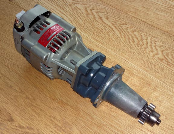
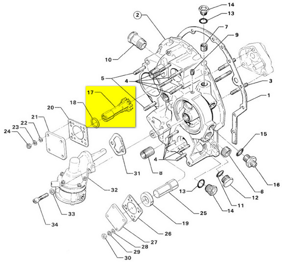
However the IO540-C4D5D has a different accessory gearbox and as this extract from its parts catalogue shows there is a blanking "shaft" (item 25) in there. If instead of the blanking shaft they put in item 17, the B&C alternator would screw straight in!
Crucially, it is obvious the hydraulic pump adaptor is not applicable to the IO540-C4D5D because - as can be seen in the above pic - the mounting flange on the adaptor is a lot bigger than the mounting flange on the B&C alternator (which is the same as a standard vacuum pump), and the blank cover plate on the unused accessory drive point is only a standard vac pump size... I obtained the adaptor cheaply on US Ebay just to see what it looks like. I had a mass of email correspondence with Lycoming but never managed to extract a clear statement from them about any of this. A lot of time was wasted on this and I think the individual in question never read past the first line of any of my emails...
Some of the B&C STCs do reference the above drive adaptor but it does not apply to the IO540-C4D5D used in the TB20.
This leaves only the following route forward:
1) Remove the cover plate on the accessory drive pad and see what kind of shaft is really behind it.
2) If it is a vac-pump-splined shaft then the IO540-C4D5D parts catalogue is wrong and somebody at Lycoming was feeling generous when they built the engine. The alternator can be simply installed, following a 337 field approval process.
3) If it is a blank shaft then the engine will have to be removed and the correct splined shaft will need to be installed. One can still proceed with the field approval process but the actual installation will need to wait till the engine comes out for an overhaul.
We had a look underneath the cover and, yeah, there was just a blank shaft...
![]()
So this will have to wait till there is a requirement to remove the accessory gearbox...
Completion
The job was finally done when the engine had enough hours to make it worth overhauling. It became clear that basically you needed to either remove the vacuum pump (by installing an avionics solution which doesn't need it, and there are some from Garmin or Aspen, etc) and then fit the B&C alternator there, or keep the vacuum system and get your hands on a variant of the IO540-C4D5D which does not have the blank shaft in that location but has the optional proper drive shaft which after all is shown in the Lycoming IPC
I did an FAA field approval, via an engineering contact in the US who presented it on my behalf to an FSDO. It cost about USD 1000 which was well worth it.
This is the B&C kit
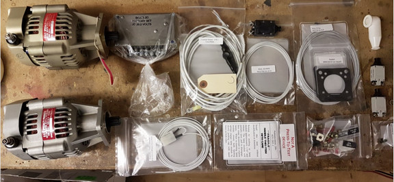
It shows a second alternator, which is a dimensional-sample-only unit which B&C sent me some years earlier to check the fit, but amazingly appears to be a fully working alternator!
This is the finished job
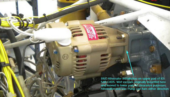
It fits nicely. You just have to be careful when changing the oil filter, to not drip oil onto it, but you need to do that anyway otherwise you will make a mess on the floor...
The alternator delivers a net 15A which is enough to power the whole TB20 in flight, if lights and possibly the pitot are turned off. I don't have any avionics which need airspeed (Aspen have an issue with that, simply shutting down totally, with latest software being able to use GPS instead, AFAIK) so turning off the pitot is viable and saves 5A.
A forum article on it and similar topics is here.
Any feedback, reports of dead links, corrections or suggestions much appreciated:
Contact details
This page last edited 11th August 2021