TB20 Vibration Analysis
This is an attempt to analyse the sources that contribute to cockpit vibration levels in the Socata TB20 aircraft.
It is a topic which has had owners (of all aircraft types) puzzled, often leading them to chase around specialist companies which can do dynamic balancing of propellers or crankshafts. Dynamic prop balancing does make a very noticeable difference; what is unclear is why doing it in flight is claimed to deliver a better result.
This article was originally written July 2008.
Procedure
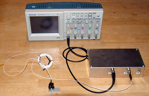
A Monitran MTN/1800 accelerometer was attached to an exposed part of the metal airframe, inside the cockpit, with the attachment point (one of the RHS rudder pedal supports) chosen to have a direct connection to the main airframe structure.
The accelerometer outputs 1 volt per G. It requires a constant current supply (around 5mA) with an open circuit voltage of 18V and this was provided with a custom built interface box.
A Tektronix TDS2004B portable digital oscilloscope was used to display the data as a Fourier Transform (FFT) which shows the frequency spectrum. This instrument can capture screen images to a USB FLASH stick, as sequentially numbered TIFF files. These images are reproduced here unaltered. Note that the vertical scale is in db i.e. logarithmic.
The oscilloscope was powered from the aircraft 28V cigar lighter socket, using a 28V to 240V inverter. The data was taken during cruise (except the idle data which was on the ground) at about 140kt and 5000ft.
Frequencies of Interest
An engine running at say 2400rpm has a crankshaft rotation frequency of 40 revs per second and any out of balance component on this would be expected to generate a line at 40Hz.
The camshaft rotates at half the crankshaft frequency i.e. 20Hz.
The 3-blade propeller would be expected to show an out of balance line at 40Hz, and any aerodynamic (slipstream impact) effects on the airframe would be expected at the 3rd harmonic i.e. 120Hz.
Exhaust effects (three combustion events per engine revolution) would be expected at the 3rd harmonic i.e. 120Hz.
It is important to note that nothing inside the engine rotates at 3x the crankshaft speed so any 3rd harmonic cannot be a simple mechanical imbalance.
Data
Fig 1 Engine idling at 1200rpm, leaned to 2.8GPH. This shows a small contribution at the 20Hz crankshaft frequency and the major peak is at the 3rd harmonic i.e. prop blade or exhaust pulse rate.
Fig 2 Full power climb, 2575 rpm. The peak is equally at the 3rd harmonic and the 6th harmonic. The fundamental barely features:
Fig 3 Economy cruise, 23"/2400rpm/11.0GPH, very slightly lean of peak. The fundamental and the 6th harmonic are buried in noise and the 3rd harmonic dominates. The other peak is at 280Hz which is at 7 times the crank frequency (bizzare).
Fig 4 The following is under same conditions as above but with the mixture enriched to 14GPH which is well rich of peak. The power output in this condition is higher, so the prop blade pitch is coarser. The rich mixture feeds the engine with excess fuel and eliminates any cylinder power balance issues. The fundamental is still nonexistent, the 3rd harmonic dominates, and the rest is similar, so uneven power delivery is not an issue in this experiment.
Fig 5 The following is at 23"/2500rpm/11GPH which is again slightly lean of peak. Apart from the slightly higher revs, the conditions are identical to Fig 3. We now have a new dominant peak at the 6th harmonic. The engine sounds noticeably smoother, which is not suprising considering how much cleaner the area around 250Hz (6th harmonic) is.
Conclusion
The most obvious thing is what is not present! The contribution from the fundamental frequency (the crankshaft and propeller speed) is negligible, except during idle when the rest of the noise is much lower. This is a most suprising result. However, this is with an engine which has been rebuilt (SB569 crank swap) by a highly reputable U.S. engine shop which dynamically balanced the crankshaft and matched up the piston and conrod weights. Moreover, the prop had just been overhauled by a very careful individual known to me personally and was then dynamically balanced on the engine. The dynamic balance was checked with accelerometers on both the front and the back of the engine and both were below 0.1 IPS (inches per second) which would be a good figure for a turbine engine. My regret is that I did not have this equipment before all this work was done; for example, when the prop was only statically balanced there was a very noticeable vibration at 1200rpm.
The second interesting outcome is that the higher harmonics dominate. The 3rd harmonic in particular is either the prop slipstream (which rotates at 3x the crank speed and this rotating airflow impacts the airframe all around), or the exhaust gases, or some engine vibration related to the exhaust event frequency.
There is also a noticeable half-crank-speed (20Hz at 2400rpm) component - it is not obvious where this could come from. Only the camshaft rotates at this speed.
A brief spectrum analysis taken from the engine mounted accelerometers (no graphic available) also shows strong contributions from the higher harmonics, suggesting that this higher order airframe vibration could well be coming from the engine and, since nothing rotates at 3x the crank speed, this must be due to the combustion event.
The other very noticeable thing is that there is a lot of energy right across the spectrum, from nearly zero (probably about 10Hz) all the way to the end of the scale which is 500Hz. This is most likely aerodynamic noise. Clearly this type of light aircraft would benefit from some heavy sound absorbing material, but the weight penalty would likely be huge and anyway it cannot be applied to the large windows.
New Results - August 2009
A year after doing the above measurements, I was starting to suspect there was something wrong with one of the fuel injectors because one cylinder was running noticeably hotter and more importantly was reaching its peak EGT at a very different fuel flow to the others. A GAMI test flight confirmed a bad mismatch on one cylinder and slightly less bad on another cylinder. It was then discovered that during the engine rebuild, done shortly before all the above measurements were done, all the six GAMI injectors has been reinstalled in random positions! Luckily, four of them ended up being well matched, which is probably why it was not too obvious.
After the injectors has been put back in the right places, a GAMI test flight confirmed the cylinder matching was back to its original (2003) GAMI-installation situation.
A quick test flight was done to see if the vibration level had improved.
Fig 6 The normal low altitude cruise setting is as per Fig 3 above (23" 2400rpm 11.0GPH LOP). The same power setting now yields the following spectrum
which shows a small drop in the dominant 3rd harmonic peak (the amplitude cursor is the M- pointer on the left). The 3rd harmonic drop is about 4db which is of the order of a 2x reduction in the vibration amplitude. However, the 6th harmonic is well up, as are some very high ones... clearly there is a complex interaction here.
Fig7 The engine does run smoother than it used to, but the bigger smoothness improvement is evident at a higher altitude, with a 20" MP (approx 10,000ft) and 9.0GPH. The following is at 2200rpm:
Unfortunately I do not have a comparative spectrum for the above power setting.
New Results March 2014
I had another dynamic balance done. There was no particular reason for it, except that the propeller had accumulated a number of nicks from stones etc and these had been smoothed out.
This time I used a new man to do the analysis, who had significantly more modern equipment than the previous person (who had retired anyway). The new equipment directly outputs data on where to attach the weight and what the weight should be. But, surprisingly, it still doesn't show a vibration spectrum like those in this article!
Fig 8: On a flight up to the airport where the work was done, I got this data
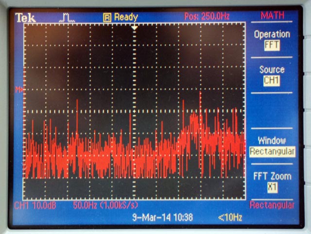
It was taken at 23", 2400rpm and 11.3USG/hr so not absolutely comparable to the results earlier in this article (Fig 3 above is the closest but that was done at 11.0 USG/hr flow rate) but the 3rd harmonic still dominates. The mysterious 7th harmonic is now missing entirely but there is some stuff higher up which are the 9th and 10th harmonics and that doesn't make any sense. (The reason Fig 8 is a photograph instead of a screen image like the others is because the screen image got saved as a CSV instead of a TIFF, and I could not find any way to plot the CSV usefully).
The vibration analyser came up with 0.21 IPS out of balance, which is quite reasonable. When the TB20 was delivered in 2002 it vibrated severely and the propeller turned out to be 1.5 IPS out of balance.
Nevertheless we had a go at reducing it, and got it down to 0.06 IPS. At that level, the analyser declares the job good enough and won't offer any more data on where to attach more weights.
Fig 9: On the return flight, also at 23", 2400rpm and 11.3 USG/hr and same altitude (2400ft) and temperature, I got this
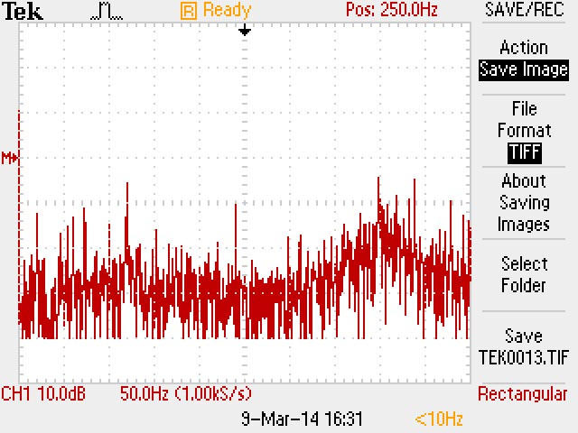
which is very similar (in the magnitude of the major peaks) as the one above it!
What does this prove? It proves that going down from 0.21 IPS to 0.06 IPS - figures as reported by the vibration analyser - does not make a detectable improvement in the airframe vibration.
So where does airframe vibration come from? Probably a lot of it comes via the severely turbulent propeller slipstream. But some could be conducted via components which run from the engine to the firewall: heater and fuel hoses, the ignition harness, etc. Also the baffle seals will transmit vibration directly from the engine to the cowling, regardless of how soft they are.
Also it is not at all clear what harmonics the vibration analyser is actually taking into account. It might be using a "total power spectrum", which may not result in a useful improvement in the cockpit because the engine mounts can be expected to preferentially absorb higher harmonics.
Despite the lack of improvement, this data is very useful because it shows that unless the propeller is badly out, the vibration in the airframe is coming from a different source. That source is probably the back of the engine (the part sitting in the engine mounts), whereas the accelerometer used in propeller balancing is attached to the front of the engine.
Last edited 9th March 2014
Any feedback, reports of dead links, corrections or suggestions much appreciated:
Contact details