By: Ric Pawell
One of the issues I've seen with my TB20 (particularly since I operate during the Australian summer) is that of high engine CHTs.
I am a great believer that keeping the CHTs of an air cooled engine within acceptable limits at all times is the key to longevity (below 400ºF for our engines), so when I began seeing north of 420º in the climb, I started an extensive investigation to determine the cause and remedy.
The answer, I found, is a bit more complex than you might imagine.
There are two key issues to consider - 1) The condition and effectiveness of the baffles, and, 2) Fuel flow to all cylinders.
This article will deal with the first of those.... the Baffles.
Baffles are there to ensure that the cooling air that enters the air inlets at the front of the cowling does its job in keeping the cylinders cool.
Simply renewing the tired old baffles may not be enough - you have to ensure that the system is configured and working effectively. The baffles serve two functions - to contain the 'ram' air mass that enters via the inlets on either side of the spinner, long enough to create a high pressure area in the compartment at the top of the engine, and to direct that airflow in such a way that it passes over the greatest possible surface area of those parts of the cylinders designed to do the cooling (the fins).
To do this, the baffles must provide an appropriate seal against the engine cowls and against each other, and be free of any unnecessary gaps and holes. Air in motion is not unlike electricity - it will take the path of least resistance - and exiting through a significant hole, or gap, is a lot easier than squeezing past layers of close-fitting fins. But this seal is not that easy to achieve within the irregularly shaped space inside our cowls and there are key areas where a lot of cooling air can be lost. The task is made even more difficult by the fact that our engines move and vibrate (the cylinders actually move in relation to each other) so unless the baffles are free to move also, they will crack or buckle and their efficiency will be diminished.
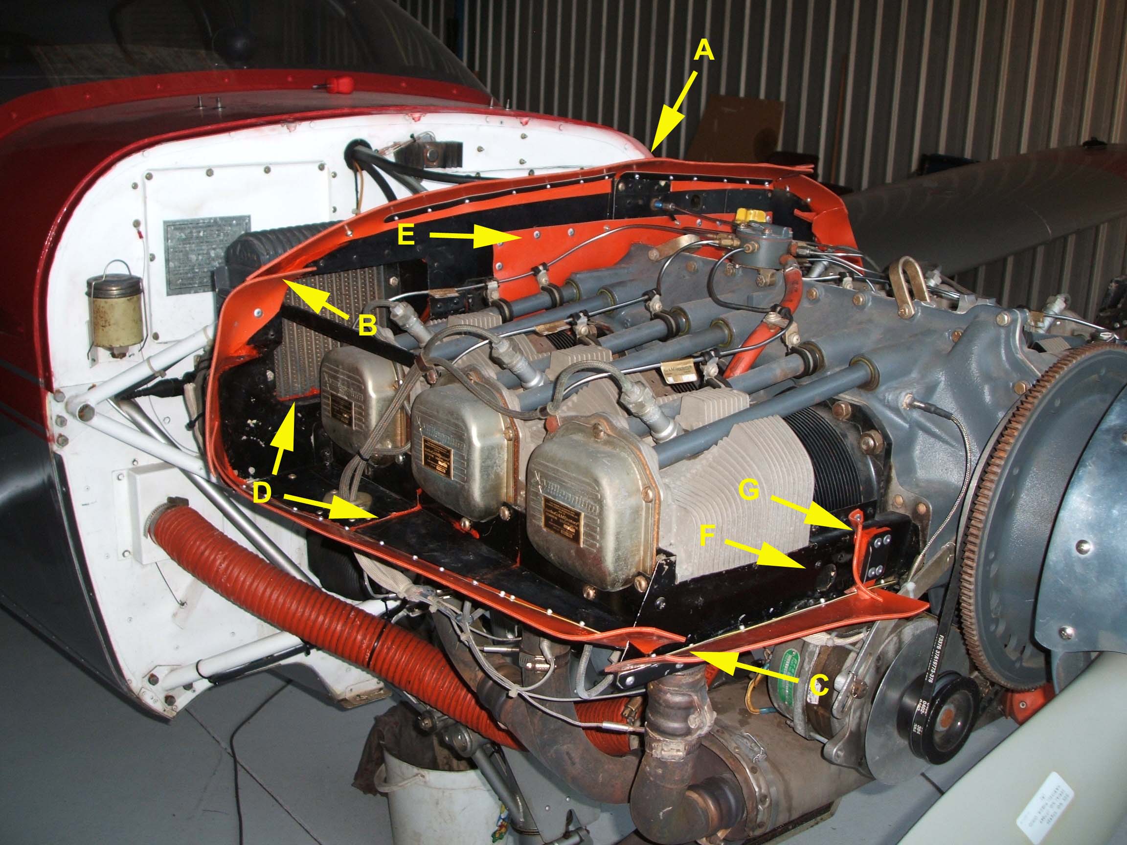
If you refer to the photo below 'Baffle Key Points', I have highlighted some
of these key areas.
The edges of the flexible baffle material must form an effective seal against the cowls (upper and lower), so their shape and length is critical - note the shape of the baffle at the position marked 'A' - this is to accommodate the 'hump' in the top cowl that streamlines it back from the spinner. The width (or height) of the material must be sufficient to form a seal without popping open when the area pressurizes in flight.
This flexible material must not be rigidly clamped together, however, particularly at the corners (e.g. B & C), otherwise, when the top cowl is positioned, a crease will form, creating a gap between the cowl and the baffle. Allowing sufficient material for intersecting segments to slide over each other works well, as they will be pressed together when the cowl pressurizes.
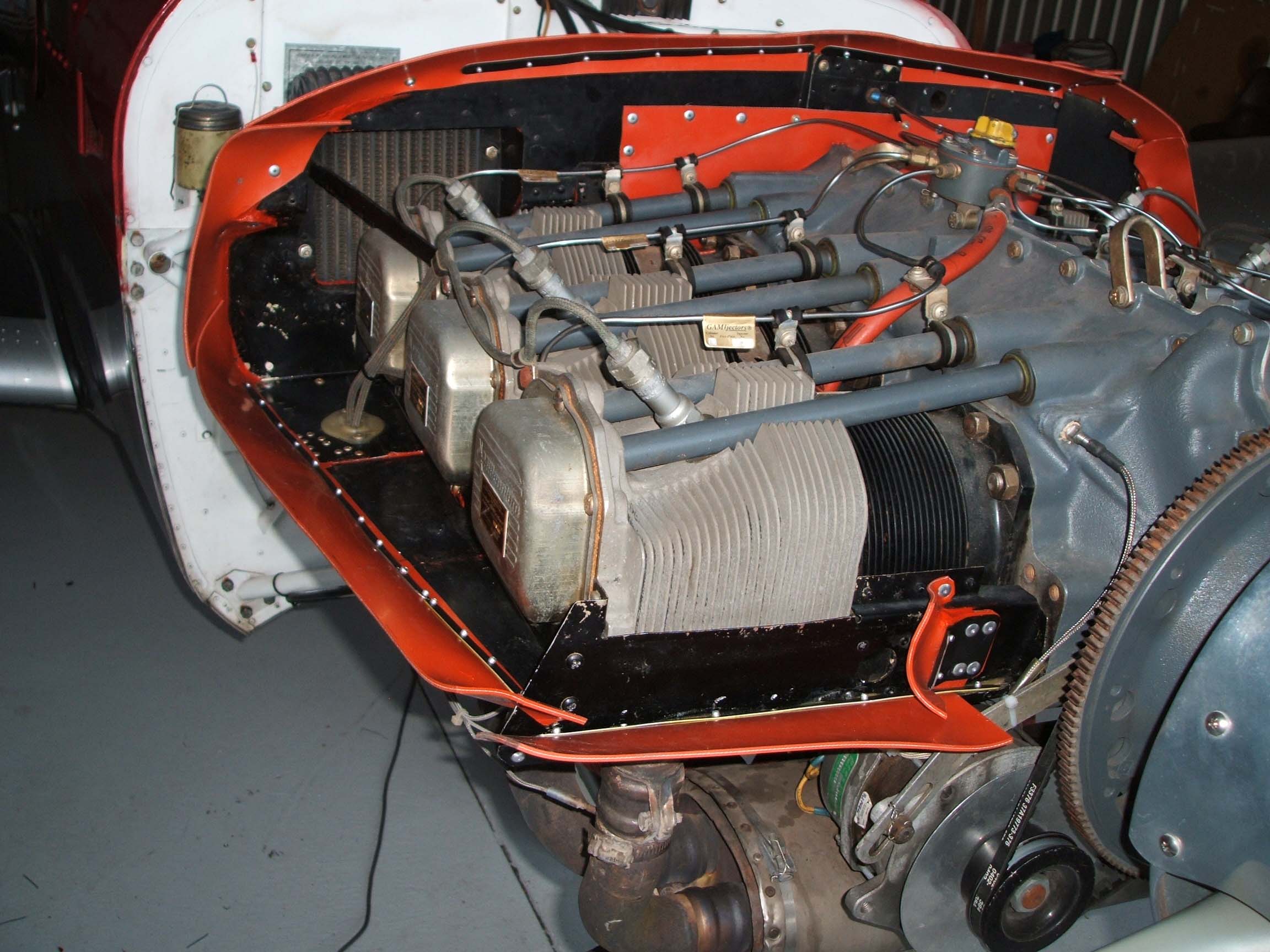
The material you see at 'E' is my own idea and not part of the original system - I think that it is critical to improved cooling. The metal bulkhead that it attaches to had a number of holes (from previous routing of cables and hoses), but the biggest outlet was the space (about a half inch) between the bulkhead baffle and the engine. This is necessary, of course, because the engine moves relative to the baffle, but it is a huge cause of wasted cooling air. The flexible material is shaped to follow the contours at the top of the crankcase, pressing down on it to seal that area completely (you will notice in the photo 'Baffles2', that it extends well down onto the cylinder bases and wraps right around the various angles of the bulkhead.
Where the metal baffle components cannot be rigidly fixed together (as in the horizontal sections marked 'D') due to their relative movement, RTV mastic does the job admirably - holding the pieces firmly together, but still allowing a degree of elasticity and flex. This material also works well to plug small holes and gaps, as you will find around the oil cooler attach points (also arrowed at 'D').
You need to ensure that in fitting the flexible baffles you do not obstruct any critical areas, or deflect air inappropriately. One such area that can be overlooked, is the cooling air inlet (marked 'F') for the alternator - I've often seen the front flexible baffle sticking straight up, or laid back, covering the inlet. I designed a flap section ('G') that seals onto the cowl inlet, creating a dam that directs air into the engine bay without obstructing the alternator cooling duct.
Finally, take a close look at the metal baffle components - vibration and rubbing up against cooling fins turned a number of mine into something that resembled the grille of a 1940s Chevvy! These are fairly easily rebuilt from new aluminum, as are any cracked, or missing, inter-cylinder baffle sections.
This was a lot of work (I’m guessing in excess of 50 hours) and I can’t imagine what a maintenance shop would charge to do it. So, the question is, was it all worth the effort?
Oh yeah! You bet!
Now, even on the hottest days, the CHTs barely nudge up toward 400º in the climb and it is virtually impossible to exceed 390º at any cruise setting, regardless of where the mixture control is set – even with OAT > 100ºF.
Ric Pawell
TB20 VH-JTW
Kewdale, western Australia
Article reproduced by kind permission of Rick Pawell
November 2008
Any feedback, reports of dead links, corrections or suggestions much appreciated:
Contact details
Update 8/2010: It is possible that silicone fabric baffle material transfers too much engine vibration to the cowlings. This company is selling what appears to be a more suitable material.